
The Standalone Power Bottleneck
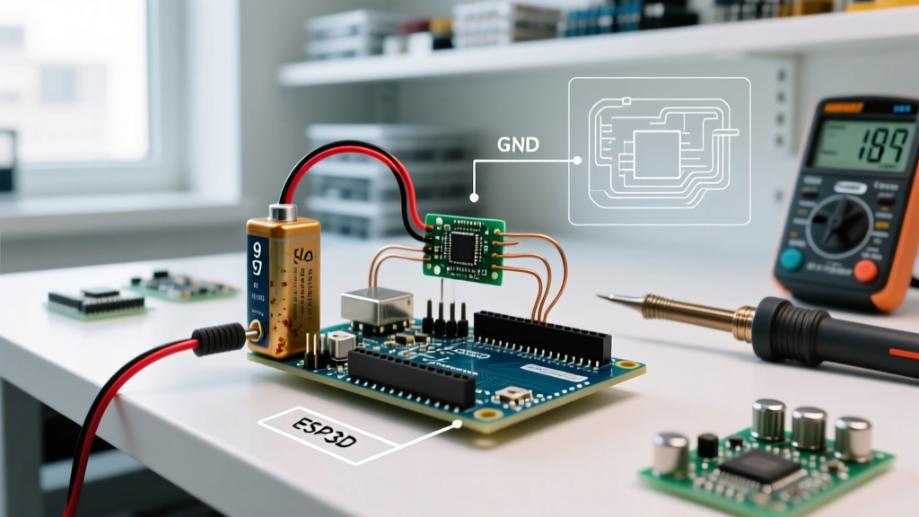
Every maker eventually transitions their project from the safety of a USB cable to a standalone power supply. Whether you are building a remote weather station powered by a 12V lead-acid battery or a motorized rover using a 9V wall adapter, the Arduino voltage regulator suddenly becomes the most critical—and most vulnerable—component on your board. While the ATmega328P microcontroller is remarkably resilient, the onboard power regulation circuitry is governed by strict laws of thermodynamics and semiconductor physics.
In 2026, despite the availability of advanced switching power trees on newer boards, millions of classic Arduino Uno R3 and Nano clones remain in circulation. These boards rely on linear regulators that are notoriously prone to thermal shutdown, voltage dropout, and brownout resets when pushed beyond their narrow operational envelopes. This guide provides a deep-dive diagnostic framework for identifying and resolving voltage regulator failures, replacing vague 'try a different power supply' advice with precise multimeter protocols and thermal calculations.
Anatomy of the Onboard Regulator
Before diagnosing a failure, you must understand the hardware. The classic Arduino Uno R3 utilizes the NCP1117ST50T3G (or the older LM1117), a linear low-dropout (LDO) regulator housed in a SOT-223 surface-mount package. Linear regulators operate by burning off excess voltage as heat. They are simple and produce clean DC output, but their efficiency is directly tied to the voltage differential.
Newer architectures, like the Arduino Uno R4, have largely abandoned linear regulation for the main 5V rail in favor of switching buck converters (such as the MP2322), which offer vastly superior thermal performance. Below is a comparative matrix of the power architectures you will encounter in the field.
| Board Model | Regulator IC | Topology | Max Safe Continuous Current (5V) | Thermal Vulnerability |
|---|---|---|---|---|
| Uno R3 / Clones | NCP1117ST50T3G | Linear LDO | ~200mA (at 12V Vin) | High (SOT-223 package) |
| Uno R4 Minima/WiFi | MP2322 / Similar | Switching Buck | 1.5A | Very Low |
| Nano V3 | Linear LDO (Varies) | Linear LDO | ~100mA (at 9V Vin) | Extreme (Minimal PCB copper) |
Error Diagnosis: 3 Common Failure Modes
1. Thermal Shutdown (The 'Hot to the Touch' Reset)
The most frequent error diagnosis for the Arduino voltage regulator is spontaneous resetting when powered via the barrel jack or Vin pin. This is almost always caused by the IC's internal thermal protection circuitry, which triggers at approximately 155°C.
To diagnose this, you must calculate the power dissipation ($P_D$). The formula is:
$P_D = (V_{IN} - V_{OUT}) \times I_{LOAD}$
Consider a scenario where you power your Uno R3 with a 12V adapter and draw 250mA from the 5V pin to run an OLED display and a servo motor. The voltage drop across the regulator is 7V (12V - 5V). The power dissipated as heat is $7V \times 0.25A = 1.75W$. The SOT-223 package has a junction-to-ambient thermal resistance ($\theta_{JA}$) of roughly 170°C/W when mounted on a standard 1-layer PCB with minimal copper pour. The temperature rise will be $1.75W \times 170 = 297°C$. The regulator will hit its 155°C thermal limit in seconds, shut down, drop the 5V rail, reset the MCU, cool down, and boot loop endlessly.
2. Dropout Voltage and Brownout Illusions
Conversely, if you attempt to power the board via Vin with a voltage that is too low—such as a sagging 6V battery pack—you will encounter dropout errors. The NCP1117 requires a minimum dropout voltage of about 1.0V to 1.2V to maintain a stable 5V output. If your input sags to 5.8V under load, the regulator output will drop to roughly 4.6V.
While 4.6V sounds sufficient, the ATmega328P's Brown-Out Detection (BOD) is typically factory-set to trigger at 4.3V. Any transient current spike (like an LED turning on) will cause a microsecond voltage dip below 4.3V, resulting in a random, unexplainable brownout reset. Diagnosing this requires an oscilloscope or a multimeter with a min/max capture function to catch the transient sag on the 5V rail.
3. USB Polyfuse Tripping
If your project resets only when connected to a PC via USB, the issue is rarely the voltage regulator itself, but rather the resettable PTC polyfuse located near the USB port. This fuse is typically rated for 500mA. If your sketch initializes a high-current peripheral (like a GSM module or a strip of WS2812B LEDs) on startup, the inrush current can trip the polyfuse. The fuse's resistance spikes, dropping the USB 5V rail below the ATmega16U2 and ATmega328P operating thresholds, causing a brownout.
Step-by-Step Diagnostic Multimeter Protocol
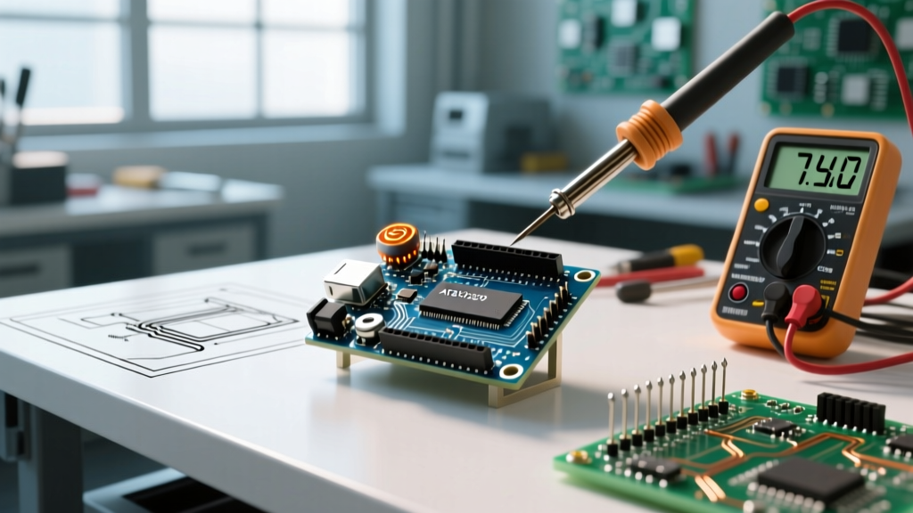
When a board exhibits erratic behavior, follow this precise diagnostic flow to isolate the Arduino voltage regulator from other systemic faults.
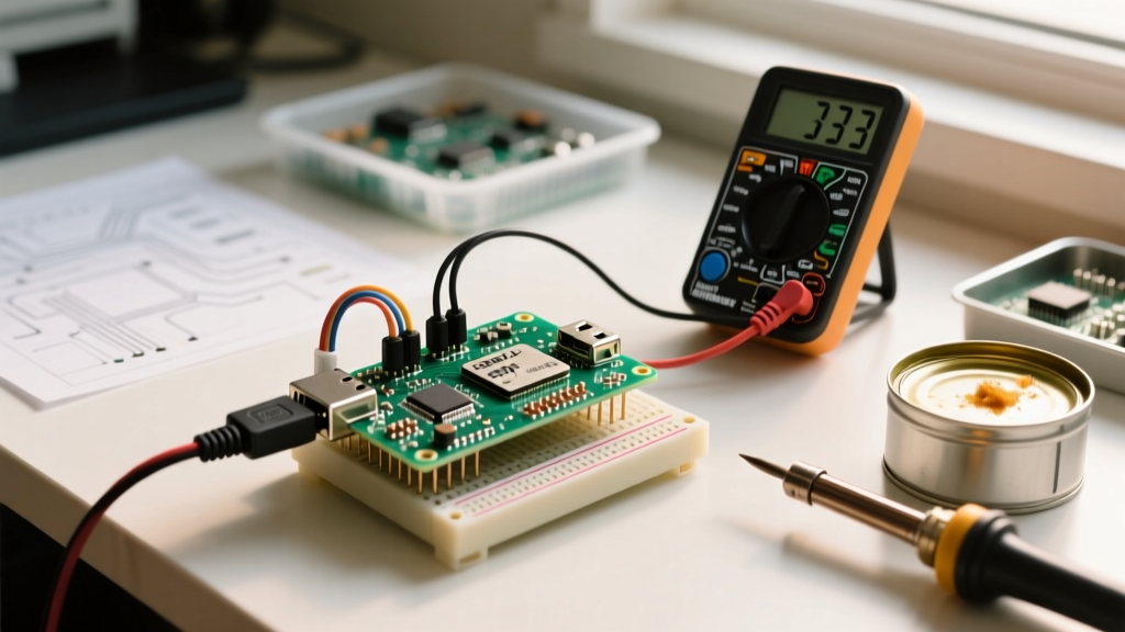
- Baseline Quiescent Draw: Power the board via USB. Set your multimeter to current (mA) mode and place it in series with the 5V output pin. A healthy Uno R3 with no peripherals should draw between 45mA and 55mA. If it draws >100mA at idle, you have a shorted peripheral or a damaged decoupling capacitor.
- Vin Stress Test: Switch to a variable bench power supply connected to the Vin pin. Set it to 7.5V. Monitor the 5V pin. It should read exactly 4.95V to 5.05V. Slowly increase the input to 12V while monitoring the 5V pin. If the 5V pin suddenly drops to 0V and the regulator IC is physically hot, you have confirmed thermal shutdown.
- AC Ripple Measurement: Switch your multimeter to AC Voltage mode (mV range). Probe the 5V pin and GND. A healthy linear regulator should show less than 5mV of AC ripple. If you see 50mV+ of ripple, the output decoupling capacitors (typically 10μF or 22μF electrolytic) have dried out and developed high Equivalent Series Resistance (ESR), a common failure on clone boards stored in humid environments.
- Thermal Imaging: Use an infrared thermometer or thermal camera. If the SOT-223 tab exceeds 110°C during normal operation, the board is operating outside its safe continuous thermal envelope, even if it hasn't triggered the 155°C hard shutdown yet.
Capacitor ESR and the Clone Board Epidemic
A frequently overlooked cause of 'regulator failure' on budget clone boards manufactured between 2020 and 2024 is the use of substandard electrolytic capacitors on the input and output stages of the NCP1117. Linear regulators require specific output capacitance and low ESR to maintain loop stability. If the output capacitor degrades, the regulator can enter high-frequency oscillation. This oscillation doesn't always manifest as a visible voltage drop on a standard multimeter, but it generates massive electromagnetic interference (EMI) and localized heating, eventually destroying the IC. If you are diagnosing a board that resets only when a specific PWM pin is toggled, suspect regulator oscillation caused by high-ESR capacitors and replace them with low-ESR ceramic or polymer alternatives.
The Hardware Fix: Bypassing the Onboard Regulator
If your diagnostic protocol confirms that your project's current requirements exceed the thermal limits of the NCP1117, do not attempt to heatsink the SOT-223 package; the thermal path to the ambient air is fundamentally flawed on a standard 1.6mm FR4 PCB. The correct engineering solution is to bypass the Arduino voltage regulator entirely using an external switching step-down (buck) converter.
Implementing the 5V Direct-Feed Method
- Component Selection: Procure a high-efficiency buck converter module. The LM2596-based modules are ubiquitous and cost around $3.50 in 2026, but they require a minimum voltage drop and are relatively bulky. For professional or compact builds, use a Pololu D24V50F5 or similar synchronous buck module ($7.00 - $9.00), which handles up to 5A with minimal heat generation.
- Wiring Protocol: Connect your external power source (e.g., a 12V battery) to the input of the buck converter. Adjust the buck converter's potentiometer until the output reads precisely 5.0V. Connect the buck converter's 5V output directly to the 5V pin on the Arduino header, and the ground to GND.
- Critical Safety Warning: When feeding 5V directly into the 5V header pin, you are backfeeding the USB-to-Serial chip and the USB port itself. Never connect a USB cable to the PC while the external 5V buck converter is active, as voltage differentials between the PC's USB 5V and your buck converter's 5V will cause destructive current loops that will fry your motherboard's USB controller. Furthermore, ensure your buck converter never exceeds 5.25V, as the ATmega328P absolute maximum rating for VCC is 6.0V, but the ATmega16U2 USB interface chip is highly sensitive to overvoltage.
Authoritative References & Further Reading
For deeper schematic analysis and component-level datasheets, refer to the following authoritative documentation:
- Arduino Uno R3 Official Hardware Documentation - Provides the exact schematic and power tree routing for the classic linear regulator layout.
- onsemi NCP1117 Datasheet - Essential for reviewing the precise thermal resistance ($\theta_{JA}$) graphs and dropout voltage curves at varying temperatures.
- Pololu Step-Down Voltage Regulators - Industry-standard reference for high-efficiency switching alternatives to linear onboard regulation.