
The Evolution of Arduino Schematic Design
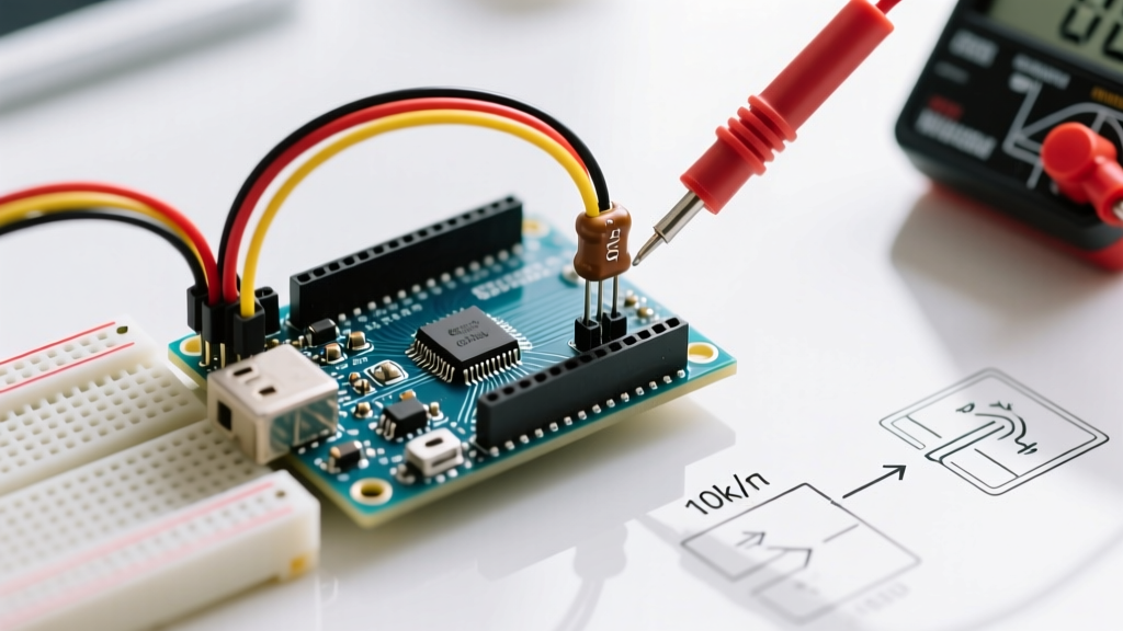
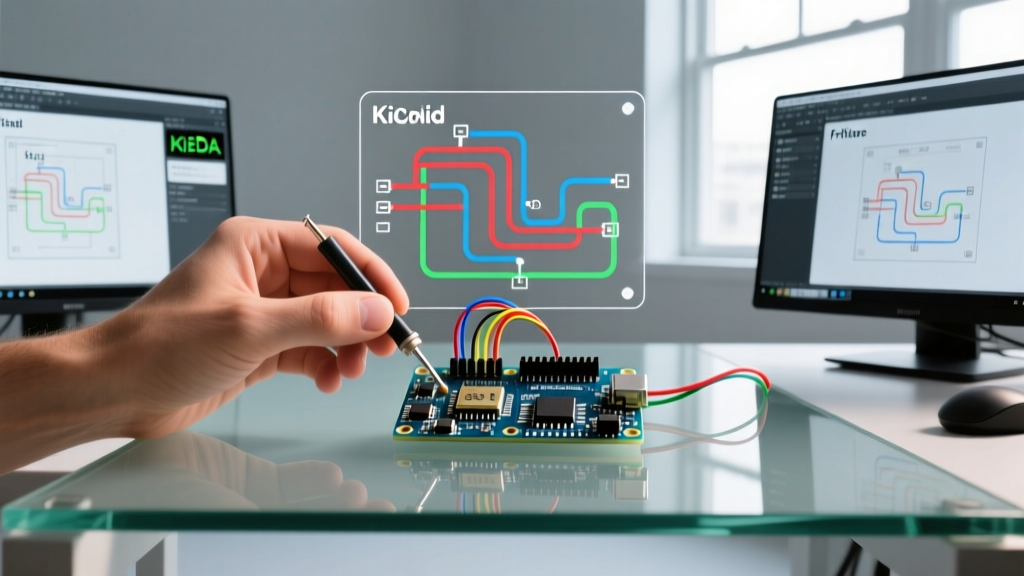
Transitioning from a messy breadboard prototype to a manufactured printed circuit board (PCB) is a major milestone for any maker. To bridge this gap, you need a reliable circuit diagram maker for Arduino projects. Historically, the maker community relied heavily on simplified, visual-first wiring tools. However, as hobbyist projects have evolved into complex, mixed-signal IoT devices requiring impedance-controlled routing and multi-layer boards, the limitations of basic wiring software have become glaringly obvious.
In 2026, the landscape of electronic design automation (EDA) tools is more accessible than ever. The paradigm has shifted from drawing 'pictures' of circuits to engineering true logical schematics that generate verified netlists. Understanding the difference between a physical wiring diagram and a logical schematic is the first step in selecting the right software for your microcontroller projects.
The Fall of Fritzing and the Rise of True EDA
For years, Fritzing was the default entry-level circuit diagram maker for Arduino enthusiasts. Its breadboard-view interface was excellent for documenting classroom projects and blog tutorials. However, Fritzing blurred the line between physical wiring and logical schematic capture. This led to widespread bad habits, such as routing power through thin jumper wires in schematics and ignoring decoupling capacitor placement.
Following Fritzing's controversial shift to a paid model (charging between $8 and $25 depending on the platform and version), the open-source hardware community experienced a mass migration. Makers moved toward professional-grade, yet highly accessible EDA suites. Today, the debate centers around two dominant platforms for custom Arduino board and shield design: KiCad and EasyEDA.
Feature Comparison Matrix: Top Arduino Schematic Tools
When selecting your software stack, consider your end goal. Are you designing a simple single-layer shield, or a custom 4-layer ATmega328P carrier board with integrated USB-C power delivery?
| Feature | KiCad (v8/9) | EasyEDA (Standard/Pro) | Fritzing (Latest) | Tinkercad Circuits |
|---|---|---|---|---|
| Primary Use Case | Complex, multi-layer custom PCBs | Rapid prototyping, direct PCBA ordering | Visual documentation, basic shields | Virtual simulation, education |
| Cost (2026) | Free (Open Source) | Free / ~$10/mo (Pro) | $8 - $25 one-time | Free (Web-based) |
| Library Management | Local, GitHub-integrated, strict symbol/footprint linking | Cloud-based, massive user-contributed LCSC library | Local, limited, frequent footprint errors | Fixed, simulation-only models |
| Netlist Verification | Advanced ERC (Electrical Rules Check) | Standard ERC | Basic / Non-existent | N/A |
| 3D Viewer | Native, ray-traced, STEP export | WebGL based, accurate | Basic visual representation | N/A |
Deconstructing the Arduino Schematic
To use a professional circuit diagram maker effectively, you must understand what actually constitutes an 'Arduino'. When you place an Arduino Uno block in a basic wiring tool, it hides the underlying engineering. In a true EDA tool, you are designing the support circuitry around the microcontroller.
If you review the official Arduino Uno R3 schematic reference, you will notice the design is broken down into distinct functional blocks. Replicating or modifying these blocks requires specific component knowledge:
1. The Microcontroller Core
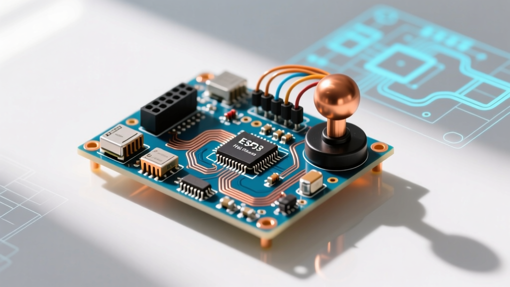
The heart of the classic Arduino is the ATmega328P. In a breadboard setup, you use the DIP-28 package (ATmega328P-PU). For custom PCBs, you will almost always select the TQFP-32 surface-mount package (ATmega328P-AU) to save board space and reduce parasitic inductance. Your schematic must correctly map all 32 pins, including the often-overlooked AVCC and AREF pins, which require their own dedicated 100nF decoupling capacitors to ground to ensure clean analog-to-digital conversions.
2. The Clock Circuit
The ATmega328P relies on an external 16MHz crystal oscillator to execute instructions at the expected timing. In your schematic, you must place the crystal (e.g., an HC49/S or a compact 3225 SMD package) as close to the XTAL1 and XTAL2 pins as possible. This requires two 22pF load capacitors tied to ground. Edge Case Warning: Using incorrect load capacitance values will cause the crystal to oscillate at the wrong frequency or fail to start up entirely in cold temperatures.
3. The Auto-Reset Mechanism
One of the most brilliant, yet poorly understood, quirks of the Arduino architecture is the auto-reset circuit. To allow the IDE to upload code without manually pressing the reset button, a 100nF capacitor is placed between the DTR (Data Terminal Ready) line of the USB-to-Serial IC and the RESET pin of the ATmega328P. When the serial port opens, the DTR line drops low, and the capacitor momentarily pulls the RESET pin low, triggering the bootloader. Missing this 100nF capacitor in your schematic means you will be manually hitting the reset button every time you compile.
Modernizing the USB Interface: CH340C vs. ATmega16U2
The official Uno R3 uses an ATmega16U2 programmed as a USB-to-Serial bridge. While highly flexible, it requires its own firmware, crystal, and complex routing. For 95% of custom maker projects in 2026, the CH340C is the superior choice for your schematic.
Pro-Tip: The CH340C includes an internal EEPROM and clock oscillator, drastically reducing the required external components. You only need the IC, a 100nF decoupling cap, and two 47-ohm series resistors on the USB D+ and D- data lines for impedance matching. This simplifies your schematic and cuts BOM costs by over $3.00 per unit.
Step-by-Step Workflow: From Schematic to PCB
Once you have selected your circuit diagram maker, follow this strict workflow to ensure your Arduino-based design is manufacturable:
- Symbol Placement: Begin by placing the logical symbols (ATmega328P-AU, AMS1117-5.0 LDO, CH340C). Group them by functional block (Power, MCU, USB, I/O).
- Power Flagging: Use explicit power flags (VCC, GND, +5V, +3V3). Never daisy-chain power through generic wires; this bypasses the software's Electrical Rules Check (ERC).
- Decoupling Strategy: Place a 100nF (0.1uF) X7R ceramic capacitor on the schematic next to every single VCC and AVCC pin. In the physical layout phase, these must be placed within 2mm of the IC pins.
- ERC Validation: Run the Electrical Rules Check. Resolve all unconnected pin warnings. If a pin is intentionally left floating (like an unused op-amp input), tie it to ground via a resistor in the schematic to satisfy the ERC.
- Footprint Assignment: Map your logical symbols to physical footprints. Ensure your AMS1117-5.0 is mapped to the correct SOT-223 package, not the TO-220 through-hole package, unless you specifically designed for through-hole assembly.
- Netlist Export: Generate the netlist and push it to the PCB layout editor. The logical connections you drew in the schematic will now dictate the 'ratsnest' (flylines) guides on your board.
Common Edge Cases and Failure Modes
Even with the best software, schematic errors will result in expensive, non-functional PCBs. Watch out for these specific Arduino-related pitfalls:
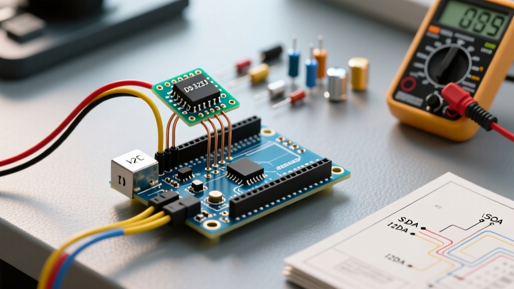
- I2C Pull-Up Resistors: The ATmega328P has internal pull-up resistors, but they are typically 20k to 50k ohms—far too weak for reliable I2C communication at 400kHz. Always add explicit 4.7k pull-up resistors to the SDA and SCL lines in your schematic when interfacing with external sensors.
- LDO Dropout Voltage: If you use an AMS1117-5.0 linear regulator to power your Arduino from a 9V battery, remember it requires a dropout voltage of about 1.1V to 1.3V. If your battery sags to 5.8V under load, your 5V rail will drop, causing the microcontroller to brownout and reset. Consider a buck converter (like the MP2359) for high-current designs.
- SPI Pin Routing: While the schematic only shows logical connections, remember that the hardware SPI pins (MOSI, MISO, SCK, SS) on the ATmega328P are tied to specific physical ports (PB3, PB4, PB5, PB2). Ensure your schematic labels match the physical port mappings if you plan to write direct register-manipulation code in C++.
Conclusion
Choosing the right circuit diagram maker for Arduino projects is about more than just drawing lines between pins; it is about adopting an engineering mindset. By moving away from simplified wiring diagrams and embracing robust EDA tools like KiCad or EasyEDA, you gain access to advanced ERC, accurate 3D modeling, and seamless PCB manufacturing pipelines. Master the logical schematic, respect the decoupling capacitors, and your custom microcontroller boards will transition from the digital canvas to physical reality without a hitch.