
The Anatomy of an Arduino with Shield Architecture
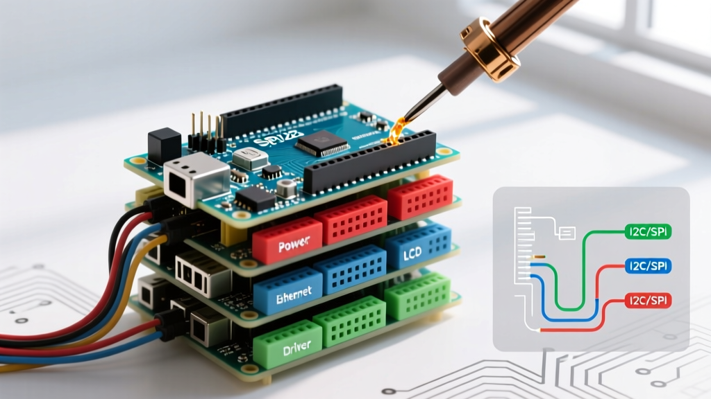
Building a modular microcontroller project often leads makers to the classic paradigm of using an Arduino with shield modules. Unlike breakout boards that require messy breadboard wiring, shields are printed circuit boards (PCBs) designed to plug directly into the standard 0.1-inch pitch female headers of an Arduino Uno, Mega, or Leonardo. They pass through all unused pins to female headers on top, allowing you to stack multiple layers of functionality—like motor control, GPS, and Ethernet—into a single, compact tower.
Concept Distinction: A shield is physically dimensioned to match the Arduino's footprint and includes pass-through stacking headers. A breakout board simply exposes the pins of a specific IC (like an MPU6050 or BME280) and requires manual jumper wire routing. Shields prioritize physical integration; breakouts prioritize flexibility.
However, simply plugging boards together is a recipe for silent failures, bus collisions, and thermal shutdowns. To successfully deploy an Arduino with shield stacks, you must understand the electrical realities of power budgeting, SPI/I2C bus arbitration, and logic-level mismatches.
Mechanical Realities and the USB Short-Circuit Risk
Before addressing software, we must address a notorious mechanical failure mode. The standard Arduino Uno R3 (and its modern successor, the Arduino Uno R4 WiFi priced around $27.50) features a metal USB Type-B or Type-C port casing. When you stack a shield directly onto the board, the solder joints on the underside of the shield often sit mere millimeters above this metal casing.
The Fix: Always apply a strip of Kapton tape (polyimide tape) over the USB port and the barrel jack of the base Arduino before stacking. Alternatively, use extra-tall stacking headers (10.5mm instead of the standard 8.5mm) to ensure adequate clearance. Failing to do this results in a dead short between the shield's ground or 5V rail and the USB port casing, instantly tripping your computer's USB overcurrent protection or frying the board's polyfuse.
Power Budgeting: The Hidden Bottleneck
The most common point of failure when stacking an Arduino with shield modules is exceeding the onboard voltage regulator's thermal limits. A standard 5V Arduino clone uses an AMS1117-5.0 linear drop-out (LDO) regulator. If you power the board via the barrel jack at 12V and your stacked shields draw 300mA, the LDO must dissipate 2.1 Watts of heat ((12V - 5V) * 0.3A). Without active cooling, the AMS1117 will hit its thermal shutdown threshold (~150°C) and drop the 5V rail, causing the MCU to brownout and reset.
Shield Power Consumption Matrix
| Shield Type | Typical Idle Draw | Peak Draw | Power Routing Recommendation |
|---|---|---|---|
| W5100 Ethernet Shield | 65 mA | 140 mA | Onboard 5V LDO is sufficient |
| 16x2 LCD + Keypad Shield | 20 mA (backlight off) | 120 mA (backlight on) | Onboard 5V LDO is sufficient |
| SIM800L / SIM900 GSM Shield | 30 mA | 2,000 mA (2A burst) | Requires external 5V 3A buck converter (e.g., LM2596) |
| Adafruit Motor Shield V2 | 10 mA (logic) | Depends on motors | Use dedicated screw-terminal power supply for motors |
Pro-Tip: If your stack includes a GSM or high-torque motor shield, bypass the Arduino's onboard regulator entirely. Wire an external step-down buck converter directly to the 5V and GND pins on the shield's pass-through headers to supply the necessary amperage without melting the base board's traces.
Navigating SPI, I2C, and UART Pin Conflicts
When you use an Arduino with shield stacks, you are forcing multiple peripherals to share the same hardware communication buses. Understanding how to resolve these conflicts is mandatory.
1. SPI Bus Collisions (The Chip Select Problem)
The Serial Peripheral Interface (SPI) bus uses shared lines for MOSI, MISO, and SCK, but requires a unique Chip Select (CS) or Slave Select (SS) pin for every single device. On the Arduino Uno, the hardware SS pin is Digital Pin 10.
- The Conflict: The classic W5100 Ethernet Shield uses Pin 10 for its Ethernet controller and Pin 4 for its onboard microSD card slot. If you stack a TFT LCD shield that also defaults to Pin 10 for its CS line, both the Ethernet chip and the LCD will attempt to drive the MISO line simultaneously, causing data corruption and bus lockups.
- The Solution: You must physically modify one of the shields. Use an X-Acto knife to carefully cut the copper trace connecting the CS header pin to the IC on the TFT shield. Then, use a jumper wire to route the CS signal to an unused digital pin (e.g., Pin 8). Update your software initialization to reflect the new CS pin:
TFT_CS = 8;.
For a deeper understanding of SPI bus arbitration and hardware requirements, refer to the official Arduino SPI documentation.
2. I2C Address Collisions
The I2C bus only uses two wires (SDA and SCL), making it highly popular for sensor and motor shields. However, every I2C device has a hardcoded hexadecimal address. If you stack an Adafruit Motor Shield V2 (default address 0x60) and an Adafruit 16-Channel PWM/Servo Shield (default address 0x40), they will coexist peacefully. But if you stack two identical sensor shields, the MCU will not be able to differentiate between them.
According to SparkFun's I2C guide, you must resolve this by altering the hardware address. High-quality shields include solder jumpers on the PCB that allow you to shift the I2C address by bridging specific pads with solder, effectively changing the address seen by the Wire library.
3. The R3 SDA/SCL Revision Quirk
If you are mixing modern shields with legacy hardware, be aware of the Arduino Uno R3 revision. The R3 added dedicated SDA and SCL pins next to the AREF pin. Older shields (pre-2012) routed I2C through analog pins A4 (SDA) and A5 (SCL). If you use a modern Mega 2560 (where I2C is on Pins 20/21) with an old Uno shield that hardwires A4/A5, the I2C bus will fail. You must use jumper wires to manually route the shield's A4/A5 pins to the Mega's dedicated SDA/SCL headers.
Logic Level Shifting: 5V vs 3.3V Ecosystems
As of 2026, the maker market is heavily divided between legacy 5V logic (classic ATmega328P boards) and modern 3.3V logic (ESP32, Arduino Nano 33 IoT, and the Uno R4 WiFi's ESP32-S3 co-processor).
If you plug a 3.3V GSM or LoRa shield into a 5V Arduino Uno, the 5V signals on the TX/RX or SPI lines will permanently destroy the shield's silicon. Conversely, a 5V shield might not recognize the 3.3V HIGH signals from a modern MCU.
The Fix: Integrate a bidirectional logic level converter (like the BSS138 MOSFET-based breakout) between the base board and the shield. Route the 5V and 3.3V supplies to the respective high/low sides of the converter, and pass your data lines through it. Never rely on simple resistor voltage dividers for high-speed SPI or I2C lines, as the parasitic capacitance will degrade the square wave into an unreadable sawtooth pattern at baud rates above 115200.
Step-by-Step: Safely Stacking a Motor and Sensor Shield
Let's look at a practical scenario: stacking the Adafruit Motor Shield V2 with a generic Data Logger Shield.
- Verify Pin Usage: The Motor Shield V2 uses I2C (SDA/SCL) exclusively for motor control, leaving SPI and UART completely free. The Data Logger uses SPI (Pins 11, 12, 13) and Pin 10 for the SD Card CS. No physical pin conflicts exist.
- Apply Isolation: Place Kapton tape over the USB port of the Arduino Uno.
- Stack Order Matters: Plug the Motor Shield directly into the Arduino. The Motor Shield's pass-through headers are robust. Plug the Data Logger shield on top. Ensure the Data Logger's coin-cell battery holder does not physically short against any solder joints on the Motor Shield beneath it.
- Separate Power Domains: Wire your 12V motor power supply to the Motor Shield's blue screw terminals. Wire a separate 5V supply to the Arduino's 5V pin to power the MCU and the SD card logic. Do not attempt to power high-torque motors through the Arduino's Vin pin.
Troubleshooting Common Shield Failures
- SD Card Fails to Initialize: If your SD card shield fails when stacked with an Ethernet shield, it is likely an SPI MISO contention issue. When the Ethernet chip is not selected (CS HIGH), it should release the MISO line into a high-impedance state. Cheap clone shields often fail to do this, holding MISO LOW and preventing the SD card from responding. Fix this by adding a 74HC125 tri-state buffer to the MISO line of the offending shield.
- Random MCU Resets: High-current shields (like relays or motors) cause voltage sags on the 5V rail when switching on. This sag drops below the ATmega328P's brown-out detection (BOD) threshold (usually 2.7V or 4.3V), triggering a reset. Solder a 470µF electrolytic capacitor across the 5V and GND pins on the shield's header to act as a local energy reservoir and smooth out transient sags.
- UART Cross-Talk: If stacking a GPS shield and a Bluetooth shield, both will attempt to use Digital Pins 0 and 1 (Hardware Serial). You must use the
SoftwareSeriallibrary to remap one of the modules to alternative digital pins (e.g., Pins 7 and 8), ensuring you do not exceed the software baud rate limits (typically 115200 bps maximum for reliable software serial).
Mastering the integration of an Arduino with shield modules transforms a fragile breadboard prototype into a robust, deployable piece of hardware. By respecting power limits, managing bus arbitration, and isolating logic levels, your stacked MCU architecture will operate reliably in real-world conditions.