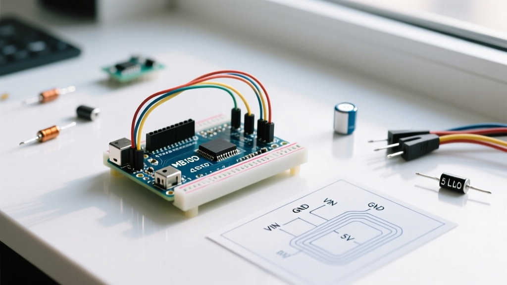

The 9V Battery to Arduino Rite of Passage: A Workflow Bottleneck
Connecting a standard 9V battery to an Arduino Uno via the barrel jack is a universal rite of passage for electronics makers. However, as projects evolve from blinking LEDs on a desk to portable, sensor-driven deployments, this naive power topology becomes a severe workflow bottleneck. The standard alkaline 9V battery paired with the Arduino’s onboard linear regulator results in abysmal power efficiency, excessive heat generation, and unpredictable voltage sag.
Optimizing your 9V battery to Arduino power workflow requires shifting from a 'plug-and-pray' mindset to a deliberate power architecture. In 2026, with the proliferation of smart voltage regulation modules and USB-C rechargeable battery form factors, there is no excuse for portable prototypes that die in under two hours. This guide dissects the physics of the standard setup and provides actionable, step-by-step workflows to maximize efficiency and runtime.
The Linear Regulator Tax: Physics and Thermal Limits
To optimize your workflow, you must first understand where the energy is going. The Arduino Uno R3 utilizes an NCP1117ST50T3G linear regulator to step the barrel jack voltage down to a stable 5V for the ATmega328P microcontroller.
Linear regulators operate by dissipating excess voltage as heat. The power dissipated ($P_{diss}$) is calculated as:
$P_{diss} = (V_{in} - V_{out}) \times I_{load}$
If you supply 9V and your Arduino circuit draws 100mA (0.1A), the regulator must drop 4V. The math: $(9V - 5V) \times 0.1A = 0.4W$. While 0.4W seems small, the SOT-223 package of the NCP1117 has a thermal resistance of roughly 50°C/W to ambient air. This means the regulator's junction temperature will rise 20°C above room temperature.
The workflow breaks down when you add peripherals. If you connect a standard servo motor and a few sensors, pushing the current draw to 400mA, the dissipation jumps to 1.6W. The junction temperature rises by 80°C. Add the 25°C ambient room temperature, and your regulator is operating at 105°C, dangerously close to its internal thermal shutdown threshold of 150°C. When thermal shutdown triggers, your Arduino resets, corrupting SD card writes and interrupting sensor logging.
Battery Chemistry: Alkaline vs. Modern Li-Ion 9V Form Factors
The traditional Energizer 522 alkaline 9V battery has a rated capacity of roughly 550mAh. However, alkaline chemistry suffers from high internal resistance. Under the continuous 100mA+ draw of a microcontroller, the terminal voltage quickly sags below the Arduino regulator's dropout voltage (typically 6.5V to maintain a stable 5V output), rendering 40% of the battery's chemical energy unusable.
The 2026 Workflow Standard: USB-C Li-Ion 9V Batteries
For rapid prototyping where the barrel jack must be used, discard alkalines. Modern makers utilize 9V-form-factor Lithium-Ion batteries (such as those from EBL or Palo). These packs contain a 3.7V Li-ion cell and an internal boost converter to output a steady 8.4V (fully charged) down to 7.0V (depleted).
- Capacity: 600mAh to 1200mAh (actual energy density is vastly superior due to flat discharge curves).
- Charging Workflow: Integrated USB-C ports eliminate the need for bulky, easily lost proprietary wall chargers.
- Voltage Sag: Near-zero internal resistance ensures the Arduino's linear regulator never starves for headroom, even during brief current spikes.
Advanced Workflow: Bypassing the Regulator with a Buck Converter
If you are building a dedicated portable node and want to squeeze every milliamp-hour out of a 9V battery, you must bypass the Arduino's inefficient linear regulator entirely. The optimal workflow uses a switching buck converter to step the 9V down to 5.1V, feeding it directly into the Arduino's 5V header pin.
According to official Arduino power documentation, supplying a regulated 5V directly to the 5V pin bypasses the onboard NCP1117 and its associated heat loss. Switching regulators like the LM2596 or the more compact MP1584EN operate at 85% to 92% efficiency, compared to the linear regulator's ~55% efficiency at 9V.
Step-by-Step Buck Converter Wiring Protocol
- Procure the Module: Source an MP1584EN adjustable buck converter module (typically $1.50 - $2.50 per unit).
- Pre-Tune the Voltage: Never connect the module to the Arduino while tuning. Power the MP1584EN input with your 9V battery. Use a digital multimeter on the output pads and turn the brass trim potentiometer until the output reads exactly 5.10V.
- Wire the Input: Connect the 9V battery snap's red wire to the module's
IN+and black wire toIN-. - Wire the Output: Connect the module's
OUT+directly to the Arduino's5Vheader pin. ConnectOUT-to the Arduino'sGNDheader pin. - Isolate the Barrel Jack: Ensure nothing is plugged into the barrel jack or USB port, as back-feeding 5V into the USB port can damage your host computer if the module's voltage accidentally drifts above 5.25V.
Power Matrix: Comparing 9V Workflow Topologies
The following table assumes a baseline continuous load of 120mA (Arduino Uno R3 + I2C OLED display + BME280 sensor).
| Power Topology | System Efficiency | Est. Runtime (600mAh 9V) | Heat Generation | Workflow Friction |
|---|---|---|---|---|
| Alkaline 9V via Barrel Jack | ~52% | 2.1 Hours | High (NCP1117 runs ~65°C) | High (Constant battery replacement) |
| Li-Ion 9V via Barrel Jack | ~55% | 3.8 Hours | Moderate | Low (USB-C rechargeable) |
| Li-Ion 9V via MP1584EN to 5V Pin | ~88% | 6.5 Hours | Negligible | Medium (Requires initial wiring/tuning) |
| 2S 18650 Li-Ion via Buck Converter | ~91% | 22+ Hours | Negligible | High (Requires battery holders/BMS) |
Edge Cases and Troubleshooting Portable Deployments
1. Servo Motor Brownouts
A common failure mode in portable 9V workflows is connecting a standard SG90 or MG996R servo directly to the Arduino's onboard 5V rail. Servos draw stall currents exceeding 800mA. No standard 9V battery snap or thin breadboard wire can deliver this current without severe voltage sag, causing the ATmega328P to brownout and reset.
The Fix: Use the 9V battery and buck converter to create a dedicated high-current 5V rail on your breadboard. Wire the servo's power and ground to this dedicated rail, and only connect the servo's PWM signal wire to the Arduino's digital pin. Ensure the Arduino GND and the buck converter GND are tied together to establish a common logic reference.
2. Deep Sleep Current Leaks
If your workflow involves putting the Arduino into deep sleep (using the LowPower library) to extend battery life for weeks, the linear regulator's quiescent current (typically 5mA to 10mA) and the onboard power LED (roughly 15mA) will drain your 9V battery faster than the microcontroller itself.
The Fix: For ultra-low-power deployments, physically desolder or clip the onboard power LED. Furthermore, abandon the 9V form factor entirely in favor of a raw 3.7V Li-Po cell feeding the 3.3V pin via an LDO, or use a barebones ATmega328P on a breadboard without the Arduino Uno's overhead circuitry.
Conclusion: Evolving Your Portable Power Strategy
The journey from plugging a disposable alkaline into the barrel jack to engineering a buck-converted, Li-ion-powered portable node marks the transition from hobbyist to embedded systems engineer. By understanding the thermal limitations of linear regulators and leveraging modern switching topologies, you transform the 9V battery from a frustrating liability into a reliable, high-density power source for your portable MCU workflows.