
Introduction to the Blinking LED Paradigm
Blinking an LED is universally recognized as the 'Hello World' of embedded systems. However, transitioning from a basic tutorial to a robust, production-ready firmware requires a deep understanding of microcontroller timing, hardware limitations, and non-blocking logic. When writing Arduino code blinking LED routines, beginners often rely on blocking functions that freeze the CPU, rendering the board useless for multitasking. In this comprehensive walkthrough, we will dissect the anatomy of LED control, moving from naive delay loops to professional state-machine architectures using modern hardware like the Arduino Uno R4 WiFi.
Hardware Selection and 2026 Pricing
Before diving into the IDE, we must establish the hardware baseline. While the classic ATmega328P-based boards remain popular, the Renesas RA4M1-powered R4 series has become the standard for new projects in 2026 due to its 32-bit Cortex-M4 core and native USB-C connectivity.
| Microcontroller Board | Core Architecture | GPIO Voltage | Avg. Retail Price (2026) |
|---|---|---|---|
| Arduino Uno R3 (Genuine) | 8-bit ATmega328P | 5V Logic | $27.00 |
| Arduino Uno R3 (Clone) | 8-bit ATmega328P (CH340G) | 5V Logic | $11.00 - $14.00 |
| Arduino Uno R4 WiFi | 32-bit RA4M1 + ESP32-S3 | 5V Logic (3.3V tolerant) | $27.50 |
For external LED wiring, you will need standard 5mm through-hole LEDs, a breadboard, jumper wires, and current-limiting resistors. According to the official Arduino Uno R4 WiFi documentation, the board features a dedicated 12x8 LED matrix alongside the traditional Pin 13 onboard LED, offering unique visual feedback opportunities without external components.
Phase 1: The Standard Delay Method (And Why It Fails)
The most common starting point for Arduino code blinking LED projects utilizes the delay() function. Here is the standard implementation:
void setup() {
  pinMode(LED_BUILTIN, OUTPUT);
}

void loop() {
  digitalWrite(LED_BUILTIN, HIGH);
  delay(1000); // CPU halts for 1000ms
  digitalWrite(LED_BUILTIN, LOW);
  delay(1000); // CPU halts for 1000ms
}
The Blocking Problem
While this code successfully blinks the LED, delay() is a blocking function. During those 2000 milliseconds, the microcontroller cannot read sensors, update displays, or process serial communication. In any real-world application involving multiple concurrent tasks, this approach leads to severe timing bottlenecks and unresponsive systems.
Phase 2: Professional Non-Blocking Architecture
To write scalable firmware, we must replace blocking delays with a time-tracking state machine using the millis() function. This approach checks the elapsed time since the board booted, allowing the loop() to execute thousands of times per second while only toggling the LED when the specific interval has passed.
The millis() State Machine Walkthrough
Below is the optimized, non-blocking implementation. This is the industry-standard method for basic timing on 8-bit and 32-bit AVR/ARM microcontrollers.
// Define constants for readability
const int LED_PIN = LED_BUILTIN;
const unsigned long BLINK_INTERVAL = 1000; // 1000ms = 1 second

// State variables
int ledState = LOW;
unsigned long previousMillis = 0;

void setup() {
  pinMode(LED_PIN, OUTPUT);
}

void loop() {
  // Capture the current time
  unsigned long currentMillis = millis();

  // Check if the interval has passed
  // This subtraction method safely handles the 49.7-day millis() overflow
  if (currentMillis - previousMillis >= BLINK_INTERVAL) {
    // Save the last time you blinked the LED
    previousMillis = currentMillis;

    // Toggle the LED state
    if (ledState == LOW) {
      ledState = HIGH;
    } else {
      ledState = LOW;
    }

    // Apply the state to the hardware
    digitalWrite(LED_PIN, ledState);
  }

  // The CPU is now free to execute other tasks here
  // e.g., readSensors(); updateDisplay();
}
Expert Insight: The 49.7-Day Overflow Edge Case
Themillis()function returns anunsigned long, which maxes out at 4,294,967,295 milliseconds (approximately 49.7 days). When it overflows, it resets to zero. By using the subtraction logic(currentMillis - previousMillis >= interval)instead of addition(currentMillis >= previousMillis + interval), the math naturally wraps around the overflow boundary without causing a system lockup. For a deeper dive into this logic, refer to the Arduino BlinkWithoutDelay official tutorial.
Hardware Deep Dive: External LED Wiring & Current Limiting
Relying solely on the onboard LED is insufficient for custom enclosures and PCB designs. When wiring external LEDs to the GPIO pins, you must calculate the exact current-limiting resistor to prevent silicon degradation.
GPIO Current Limitations
According to the Arduino Uno Rev3 hardware specifications, the absolute maximum DC current per I/O pin is 40mA. However, operating continuously at this threshold causes thermal stress on the ATmega328P die. The recommended continuous current is 20mA. Exceeding this limit repeatedly will eventually fry the GPIO port, rendering the pin permanently dead.
Resistor Calculation Matrix
Using Ohm's Law (R = (V_source - V_forward) / I_forward), we can determine the exact resistor required for various LED colors. Assuming a 5V GPIO output and a target current of 20mA (0.02A):
| LED Color | Typical Forward Voltage (Vf) | Calculated Resistance | Standard E12 Resistor Value |
|---|---|---|---|
| Red (5mm) | 2.0V | (5 - 2.0) / 0.02 = 150Ω | 150Ω or 180Ω |
| Green (5mm) | 2.2V | (5 - 2.2) / 0.02 = 140Ω | 150Ω |
| Blue (5mm) | 3.2V | (5 - 3.2) / 0.02 = 90Ω | 100Ω |
| White (5mm) | 3.4V | (5 - 3.4) / 0.02 = 80Ω | 82Ω or 100Ω |
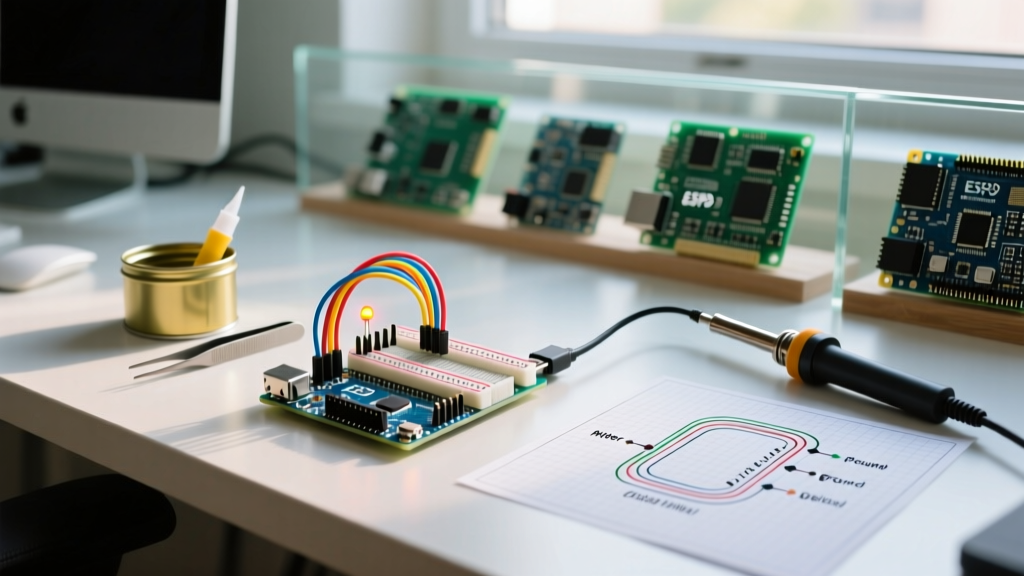
Wiring Topology: Connect the GPIO pin to the anode (long leg) of the LED via the calculated resistor. Connect the cathode (short leg, flat side) directly to the GND rail. Never wire an LED directly to a 5V pin without a resistor, as the current draw will spike to >100mA, instantly destroying the LED junction and potentially damaging the microcontroller's voltage regulator.
Phase 3: Advanced Walkthrough - PWM Fading
Digital toggling only provides ON/OFF states. To achieve analog-like brightness control, we utilize Pulse Width Modulation (PWM). On the Uno R3, PWM is available on pins 3, 5, 6, 9, 10, and 11 (denoted by the ~ symbol). The Uno R4 WiFi offers 12-bit DAC capabilities and hardware PWM on almost all digital pins.
const int PWM_LED_PIN = 9; // Must be a PWM-capable pin

void setup() {
  pinMode(PWM_LED_PIN, OUTPUT);
}

void loop() {
  // Fade in (0 to 255)
  for (int fadeValue = 0; fadeValue <= 255; fadeValue += 5) {
    analogWrite(PWM_LED_PIN, fadeValue);
    delay(30); // Short delay is acceptable here for visual smoothing
  }

  // Fade out (255 to 0)
  for (int fadeValue = 255; fadeValue >= 0; fadeValue -= 5) {
    analogWrite(PWM_LED_PIN, fadeValue);
    delay(30);
  }
}
Troubleshooting Edge Cases and Failure Modes
Even with correct code, hardware anomalies can disrupt your Arduino code blinking LED deployment. Use this diagnostic checklist when your circuit fails:
- LED Remains Dim or Flickers: This usually indicates a voltage drop on the breadboard rails or an inadequate power supply. If powering via USB, ensure the port can supply at least 500mA. Add a 100nF ceramic decoupling capacitor across the 5V and GND rails near the LED to filter high-frequency noise.
- GPIO Pin Unresponsive: If you previously wired an LED without a resistor, the internal trace of the ATmega328P may have burned out. Test the pin with a multimeter in continuity mode. If dead, reassign your code to an alternate GPIO pin.
- Millis() Timing Drift: If your blink interval slowly drifts out of sync over hours, you are likely using
previousMillis = currentMillisinside a slightly delayed loop. Instead, usepreviousMillis += BLINK_INTERVALto maintain absolute mathematical precision regardless of loop execution time. - Back-EMF Spikes (Relay/Large LED Arrays): If you are switching high-power LED strips via a MOSFET, ensure you have a flyback diode and a 10kΩ pull-down resistor on the MOSFET gate to prevent floating gate states during microcontroller boot-up.
Summary
Mastering LED control is the foundational stepping stone to complex embedded systems. By moving away from blocking delay() functions and adopting millis() state machines, calculating precise current-limiting resistors, and respecting GPIO current thresholds, you ensure your hardware remains reliable and your firmware remains scalable. Whether you are deploying a simple status indicator on an Uno R3 or building a complex IoT node on the Uno R4 WiFi, these principles remain the bedrock of professional microcontroller programming.