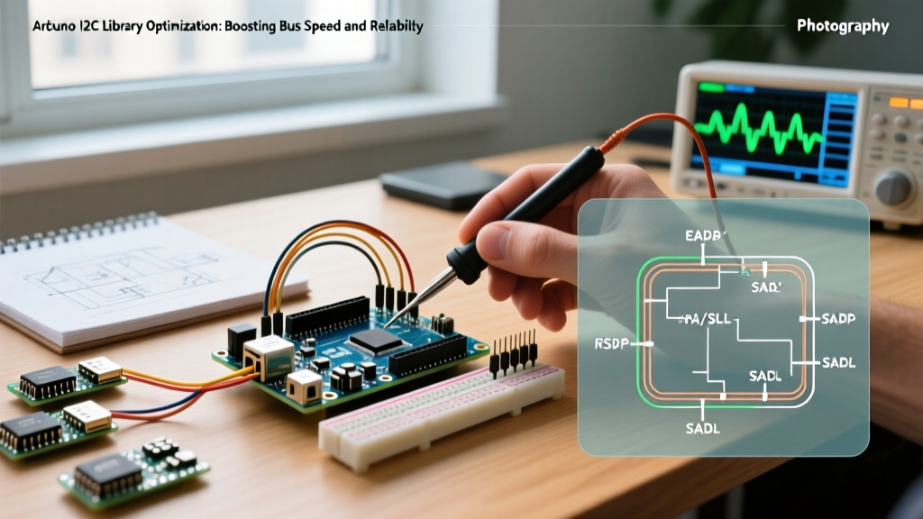

The Bottleneck of Default I2C Configurations
When prototyping with microcontrollers, the Inter-Integrated Circuit (I2C) protocol is the undisputed workhorse for connecting sensors, displays, and EEPROMs. However, the default implementation of the Arduino I2C library (commonly invoked via Wire.h) prioritizes broad hardware compatibility and safety over raw throughput. Out of the box, it limits bus speed to 100kHz (Standard Mode) and restricts the internal buffer to a mere 32 bytes. For modern high-speed sensor fusion applications—such as polling a BNO085 IMU at 400Hz or reading large OLED frame buffers—these defaults introduce severe latency and data truncation.
In this guide, we will dissect the architectural limitations of the standard library and explore advanced optimization techniques, from direct register manipulation on AVR chips to leveraging DMA on modern ESP32-S3 boards in 2026.
Bypassing the 100kHz Default: Clock Rate Configuration
The most immediate optimization is increasing the clock frequency. The I2C specification defines Fast Mode (400kHz) and Fast Mode Plus (1MHz). You can instruct the Arduino I2C library to use Fast Mode by calling Wire.setClock(400000); immediately after Wire.begin();.
However, simply changing the software clock speed is only half the battle. The physical layer must support the higher frequency. According to the NXP I2C-bus specification, the bus capacitance must not exceed 400pF. As frequency increases, the RC time constant of the pull-up resistors and bus capacitance becomes the limiting factor for signal rise times.
Calculating Optimal Pull-Up Resistors
If you push the bus to 400kHz or 1MHz without adjusting your pull-up resistors, you will encounter corrupted bytes and NACK errors. The minimum pull-up resistance is dictated by the maximum sink current ($I_{OL}$), typically 3mA for standard I2C pins.
- For 3.3V Logic (e.g., ESP32, SAMD21): $R_{p(min)} = (3.3V - 0.4V) / 0.003A = 966\Omega$. A 1kΩ resistor is ideal for 1MHz Fast Mode Plus.
- For 5V Logic (e.g., ATmega328P): $R_{p(min)} = (5.0V - 0.4V) / 0.003A = 1533\Omega$. A 2.2kΩ resistor is the standard choice for 400kHz Fast Mode.
Pro Tip: Avoid using the internal microcontroller pull-up resistors (often 20kΩ to 50kΩ) for high-speed I2C. They are far too weak to pull the bus high within the strict timing windows of Fast Mode.
Overcoming the 32-Byte Buffer Limitation
A notorious edge case when using the standard Arduino I2C library is the hardcoded 32-byte buffer limit, defined by BUFFER_LENGTH in the library's source code. If you attempt to read a 64-byte FIFO burst from an MPU6050 accelerometer in a single Wire.requestFrom() call, the library will silently truncate the data, leading to catastrophic failures in your sensor fusion algorithms.
Solution 1: Modifying the Core Library
For AVR-based boards, you can navigate to your Arduino IDE installation directory, locate hardware/arduino/avr/libraries/Wire/src/Wire.h, and change #define BUFFER_LENGTH 32 to 64 or 128. Be aware that this consumes precious SRAM (the ATmega328P only has 2KB total).
Solution 2: Using I2Cdevlib
A superior, non-destructive approach is utilizing Jeff Rowberg's I2Cdevlib. This alternative library bypasses the standard buffer limitations by implementing its own robust I2C transaction handling, allowing seamless FIFO burst reads without modifying core IDE files. It remains one of the most reliable frameworks for complex IMU integration.
AVR Direct Register Manipulation for Ultra-Low Latency
While the official Arduino Wire reference provides a clean API, the abstraction layer introduces function call overhead and interrupt latency. For time-critical applications on the ATmega328P (such as reading an ADC or IMU inside a 1kHz control loop), bypassing Wire.h entirely and manipulating the Two-Wire Interface (TWI) registers directly yields massive performance gains.
The TWBR Math
The I2C clock speed on AVR is controlled by the TWI Bit Rate Register (TWBR) and the prescaler bits in the TWI Status Register (TWSR). The formula is:
SCL = F_CPU / (16 + 2 * TWBR * 4^TWSR)
Assuming a 16MHz crystal and a prescaler of 0, achieving exactly 400kHz requires:
TWBR = ((16000000 / 400000) - 16) / 2 = 12
// Direct AVR I2C Initialization for 400kHz
void fast_i2c_init() {
    TWSR = 0x00; // Set prescaler to 0
    TWBR = 12;   // Set bit rate for 400kHz at 16MHz
    TWCR = (1<<TWEN); // Enable TWI
}
By writing custom, blocking TWI state-machine functions, you eliminate the overhead of the Arduino interrupt service routines (ISRs), reducing byte-transfer latency by up to 40%.
ESP32-S3 and DMA-Driven I2C in 2026
The landscape of microcontrollers has shifted dramatically. In 2026, the ESP32-S3 and ESP32-C6 are the dominant platforms for edge AI and IoT. The ESP32 architecture handles I2C fundamentally differently than AVR. The standard Wire.h implementation on ESP32 is actually a wrapper around the ESP-IDF's underlying I2C driver.
For maximum performance optimization on ESP32, you should bypass the Arduino wrapper and use the ESP-IDF I2C Master API directly. This allows you to leverage the ESP32's 128-byte hardware FIFO and Direct Memory Access (DMA). With DMA, the I2C peripheral transfers bulk sensor data directly into RAM without waking the CPU for every single byte, freeing up the dual-core Xtensa LX7 processors to run neural network inference tasks concurrently.
Handling Clock Stretching and NACK Edge Cases
High-speed I2C networks are prone to bus lockups, primarily caused by 'clock stretching'—where a slave device holds the SCL line low to buy processing time. If a slave crashes while stretching the clock, the master will hang indefinitely.
To prevent this, modern iterations of the Arduino I2C library include timeout configurations. Always implement a timeout in your initialization sequence:
Wire.begin();
Wire.setWireTimeout(25000, true); // 25ms timeout, reset_on_timeout = true
This ensures that if a sensor locks the bus, the master will automatically reset the TWI peripheral and attempt a clean recovery, a critical feature for unattended remote deployments.
Library and Architecture Comparison Matrix
| Feature | Standard Wire.h (AVR) | I2Cdevlib (AVR/ESP) | ESP-IDF Native I2C (ESP32-S3) |
|---|---|---|---|
| Max Practical Speed | 400kHz (Fast Mode) | 400kHz (Fast Mode) | 1MHz+ (Fast Mode Plus) |
| Buffer Limit | 32 Bytes (Hardcoded) | Dynamic / Custom | 128B FIFO + DMA |
| CPU Overhead | High (ISR per byte) | High (ISR per byte) | Ultra-Low (DMA) |
| Timeout Handling | Native (via setWireTimeout) | Manual Implementation | Native Hardware/Driver |
| Best Use Case | Basic sensors, low-speed logging | Complex IMUs, FIFO bursts | Edge AI, high-freq sensor fusion |
Summary of Best Practices
Optimizing the Arduino I2C library requires a holistic approach that bridges software configuration and hardware physics. Always match your pull-up resistors to your target clock speed and bus capacitance. If you are reading large data bursts, abandon the default 32-byte buffer by adopting I2Cdevlib or modifying core headers. Finally, for mission-critical deployments, implement bus timeouts to gracefully handle clock-stretching anomalies. By applying these targeted optimizations, you can transform a sluggish, unreliable I2C bus into a high-speed, robust data pipeline capable of supporting the most demanding embedded applications.