
The Hardware Landscape: Choosing Your 13.56 MHz Transceiver
When integrating RFID and Arduino for access control, attendance logging, or inventory tracking, the 13.56 MHz high-frequency band is the industry standard. It supports ISO/IEC 14443 Type A and MIFARE protocols, offering a balance of read speed, security, and cost. However, treating all RFID readers as simple plug-and-play serial devices is a critical mistake that leads to bus contention, fried logic gates, and abysmal read ranges.
Before writing a single line of C++, you must select the correct transceiver IC. The market is dominated by two distinct architectures: the NXP MFRC522 and the NXP PN532. Below is a technical comparison to guide your hardware selection for 2026 projects.
| Feature | MFRC522 (Standard RC522 Module) | PN532 (Adafruit/Elecrow Modules) |
|---|---|---|
| Primary Protocols | ISO14443A / MIFARE Classic & Ultralight | ISO14443A/B, MIFARE, FeliCa, NFC (Type 1-4) |
| Host Interfaces | SPI, I2C, UART (DIP switches on some boards) | SPI, I2C, HSU (UART) via onboard DIP switches |
| Max SPI Clock | 10 MHz | 5 MHz (SPI), 400 kHz (I2C) |
| Typical Module Cost | $1.50 – $3.00 USD | $6.50 – $12.00 USD |
| NFC Peer-to-Peer | No (Reader/Writer only) | Yes (Initiator and Target modes) |
SPI Protocol Mechanics: Driving the MFRC522
The MFRC522 is the undisputed budget king for basic MIFARE Classic 1K reading. When communicating via SPI, the RC522 operates strictly in SPI Mode 0 (CPOL=0, CPHA=0). This means the clock idles low, and data is sampled on the rising edge of the clock signal.
Clock Speed and Bus Contention
While the Arduino Uno (ATmega328P) can push SPI clocks up to 8 MHz (half of its 16 MHz system clock), the NXP MFRC522 datasheet specifies a maximum SPI clock frequency of 10 MHz. In practice, pushing the SPI bus to 8 MHz on long jumper wires (>15cm) causes signal degradation due to parasitic capacitance. For stable operation on a breadboard, initialize the SPI bus at 4 MHz using the Arduino SPI library:
SPI.beginTransaction(SPISettings(4000000, MSBFIRST, SPI_MODE0));
The 3.3V Logic Trap: Preventing Silicon Death
CRITICAL WARNING: The MFRC522 and PN532 ICs operate at 3.3V logic. The ATmega328P on the Arduino Uno and Mega outputs 5V on its MOSI, SCK, and SS pins. Feeding 5V directly into the RC522's MISO or control lines will degrade the internal ESD protection diodes over time, leading to intermittent 'Authentication Failed' errors before ultimate silicon death.
To safely interface RFID and Arduino hardware, you must implement logic level shifting. Do not rely on simple resistor voltage dividers for high-speed SPI lines; the RC divider's RC time constant will round off the square wave edges at 4 MHz, causing missed bits.
- Best Solution: Use a dedicated MOSFET-based bidirectional level shifter (e.g., BSS138 breakout board, ~$1.50).
- Alternative (Unidirectional): Use a CD4050B hex non-inverting buffer powered at 3.3V for the MOSI, SCK, and SS lines. Connect the MISO line directly to the Arduino, as 3.3V is generally recognized as a logical HIGH by the 5V ATmega328P (V_IH min is typically 0.6 * VCC, or 3.0V, making 3.3V marginally safe, though a level shifter is preferred for strict compliance).
I2C and the PN532 Alternative
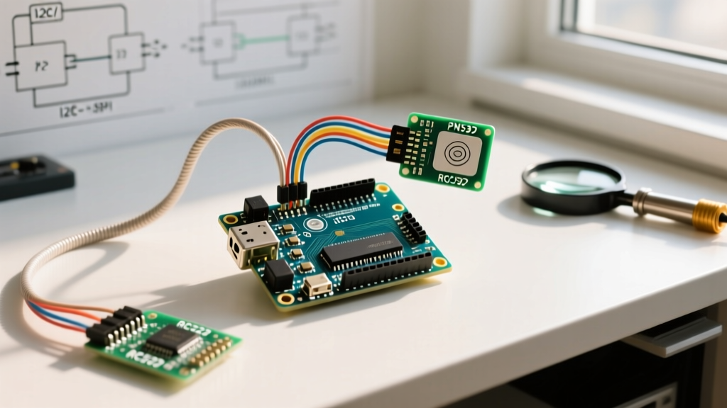
If your project requires reading NTAG215 (commonly used for Nintendo Amiibos and modern NFC tags) or engaging in NFC peer-to-peer communication, the PN532 is mandatory. The PN532 handles the heavy lifting of the ISO14443-4 protocol stack internally, exposing a clean UART or I2C interface to the microcontroller.
When wiring the PN532 via I2C, ensure the onboard DIP switches are set correctly (typically Switch 1 ON, Switch 2 OFF for I2C). The default I2C address is 0x24. A common failure mode in multi-sensor I2C buses is address collision. Unlike standard sensors, the PN532 does not have hardware pins to change its I2C address easily. If you must share the bus with another device locked at 0x24, you must implement an I2C multiplexer like the TCA9548A.
Wakeup and Handshake Timing
The PN532 requires a specific hardware wakeup sequence via the IRQ pin before it will respond to I2C polling. According to the Adafruit PN532 integration guide, the host must pull the IRQ pin LOW for at least 2ms, then release it HIGH, before sending the first I2C start condition. Failing to implement this handshake results in the Arduino receiving NACK (Not Acknowledged) on the I2C bus.
Code Optimization: Moving Beyond Blocking Polls
The most common mistake in RFID and Arduino tutorials is placing the card detection function inside a tight, blocking loop(). Calling PICC_IsNewCardPresent() continuously hogs the SPI bus, starving other peripherals (like an SD card or Ethernet shield sharing the same bus) and maxing out CPU utilization.
Interrupt-Driven Architecture
For production-grade firmware, transition from polling to interrupt-driven reading. While cheap RC522 breakout boards often omit the IRQ pin, the PN532 exposes it. Configure the PN532 to trigger an interrupt on the Arduino's INT0 (Pin 2) or INT1 (Pin 3) when a tag enters the RF field.
- Configure the PN532 to auto-poll using the
InAutoPollcommand. - Put the Arduino into
LowPower.powerDown()or standard sleep mode. - When a MIFARE tag enters the 13.56 MHz field, the PN532 pulls the IRQ pin LOW.
- The Arduino wakes via ISR (Interrupt Service Routine), sets a volatile boolean flag, and processes the UID in the main loop.
This approach reduces power consumption from ~45mA to under 5mA, making it viable for battery-operated 18650 Li-ion deployments.
Real-World RF Troubleshooting and Edge Cases
Even with perfect code and level shifting, RF physics will dictate your success. Here are three specific failure modes and their engineered solutions:
1. Antenna Detuning on Metal Surfaces
If you mount your RC522 module inside a metal enclosure or directly onto an aluminum extrusion, the conductive surface creates eddy currents that oppose the reader's magnetic field. This detunes the 13.56 MHz LC tank circuit, dropping your read range from 5cm to less than 2mm.
Solution: Place a flexible ferrite sheet (typically 0.1mm to 0.3mm thick, rated for >10 MHz) between the PCB antenna and the metal surface. The ferrite absorbs the magnetic flux and prevents eddy current formation, restoring the read range to ~4cm.
2. MIFARE Classic Sector Authentication Failures
Reading the UID is trivial; reading the memory blocks requires sector authentication. A frequent bug occurs when developers attempt to read Sector 1 using the default key (0xFFFFFFFFFFFF) after a tag has been written by a commercial access system. Commercial systems overwrite Sector 0, Block 3 (the Sector Trailer) with custom Key A and Key B values.
Solution: Always use the PCD_Authenticate function with the correct key type (PICC_CMD_MF_AUTH_KEY_A or B). If you lock yourself out of a MIFARE Classic tag by writing an unknown key to the trailer block, the tag is permanently bricked for that sector. There is no hardware backdoor to reset MIFARE Classic keys.
3. SPI Bus Ghosting with Multiple Slaves
When sharing the SPI bus with an Ethernet module (like the W5500) and an RC522, failing to tri-state the MISO line of the inactive device will cause data corruption. The Arduino SPI reference documentation emphasizes the importance of proper Chip Select (CS) management.
Solution: Ensure every SPI device library you use properly releases the bus by setting its CS pin HIGH and configuring its MISO pin as INPUT (high impedance) when not selected. If a module lacks hardware tri-state logic on MISO, you must route its MISO line through a 74HC125 tri-state buffer gated by the CS pin.
Summary
Successfully merging RFID and Arduino requires moving beyond copy-pasted wiring diagrams. By respecting the 3.3V logic thresholds, understanding SPI Mode 0 timing constraints, and mitigating RF detuning with ferrite materials, you elevate your project from a fragile breadboard prototype to a robust, deployable access control system.