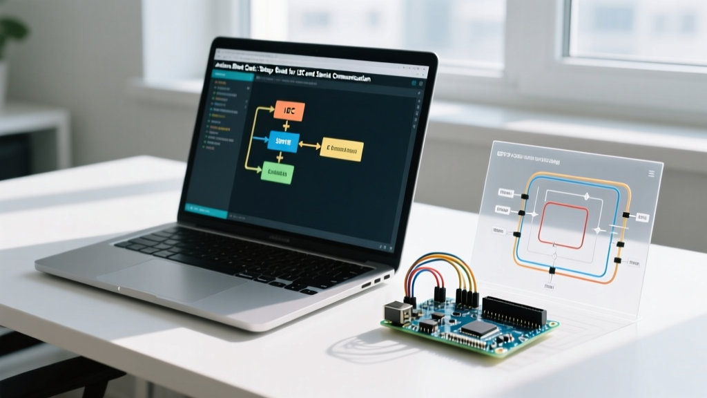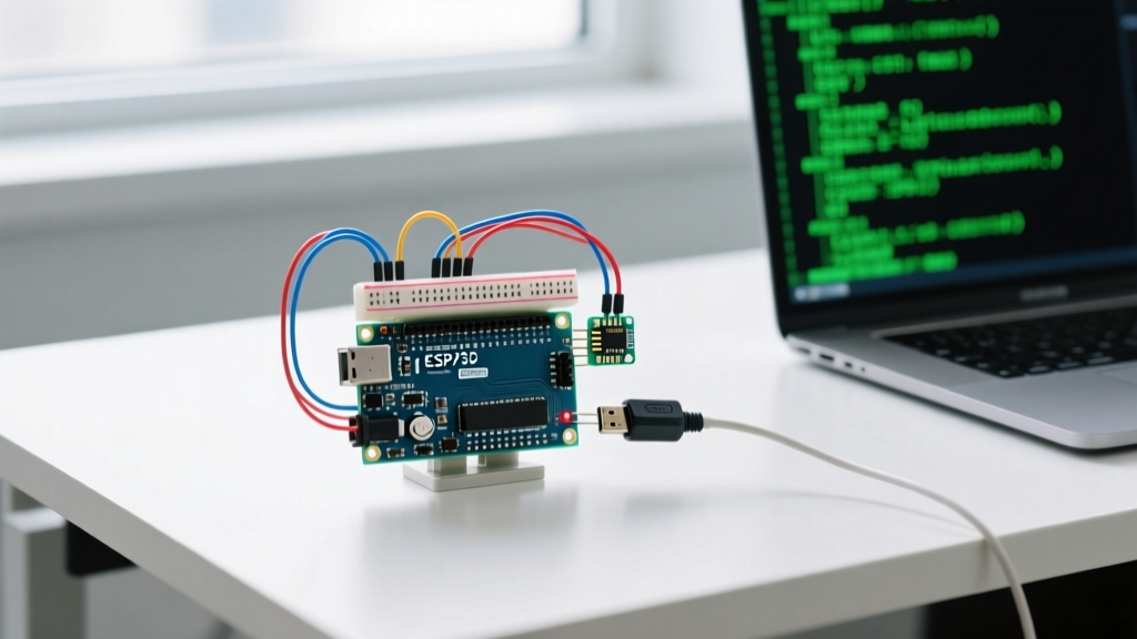

When debugging a UART Arduino setup, engineers and hobbyists often encounter the dreaded 'garbage characters' in the serial monitor or complete communication blackouts. Universal Asynchronous Receiver-Transmitter (UART) is the backbone of microcontroller debugging, sensor integration, and module communication. Yet, despite its conceptual simplicity, UART lacks a dedicated hardware clock line, making it highly susceptible to timing drift, voltage mismatches, and buffer overflows.
In this comprehensive troubleshooting guide, we dissect the most common UART Arduino failures at both the physical and data-link layers. Whether you are interfacing an ATmega328P with an ESP32 or debugging a custom PCB, these component-level solutions will help you isolate faults and restore flawless serial transmission.
The Anatomy of a UART Arduino Failure
UART communication relies on precise timing and shared electrical references. Unlike SPI or I2C, there is no SCL (clock) line to synchronize the transmitter and receiver. Both devices must independently agree on the baud rate, start bit, data bits, parity, and stop bits. A failure in any of these parameters—or a degradation of the physical signal—results in framing errors or corrupted payloads. To systematically debug a UART Arduino connection, we must divide the problem into two domains: the Physical Layer (hardware and wiring) and the Data Link Layer (software and timing).
Hardware-Level Troubleshooting (Physical Layer)
Before questioning your C++ code, verify the electrical integrity of your TX and RX lines. Over 60% of serial communication failures stem from physical layer misconfigurations.
Voltage Level Mismatches (5V vs 3.3V Logic)
The classic Arduino Uno (ATmega328P) operates at 5V logic, while modern peripherals like the ESP32, STM32, and most GPS modules operate at 3.3V. Connecting a 5V TX line directly to a 3.3V RX pin can permanently damage the peripheral's silicon due to overvoltage on the GPIO protection diodes.
Actionable Fixes:
- Voltage Divider: For a quick prototype, use a resistor voltage divider on the 5V TX line. A 1kΩ series resistor and a 2kΩ pull-down resistor will drop 5V down to a safe 3.33V. This costs less than $0.10 but is only suitable for lower baud rates (under 115,200) due to RC time constant delays introduced by parasitic capacitance.
- MOSFET Level Shifter: For high-speed UART (up to 1 Mbps), use a bi-directional logic level converter based on the BSS138 N-channel MOSFET. These modules are widely available for roughly $1.20 and provide clean, fast edge transitions without signal degradation.
- Dedicated ICs: For production environments, integrate a Texas Instruments TXS0108E or a Nexperia NXS0102 auto-direction sensing level translator.
The Missing Ground Reference
A surprisingly common mistake is connecting only the TX and RX wires between two independently powered microcontrollers. UART is a single-ended signaling protocol, meaning the voltage is measured relative to ground. Without a common GND connection, the receiver's reference plane floats, leading to erratic framing errors.
Expert Tip: Always connect the GND pins of both devices first. If the devices are powered by separate wall adapters or isolated power supplies, ensure they share a common earth ground or use an isolated digital isolator IC like the Analog Devices ADuM1201 to bridge the serial lines safely.
Software & Configuration Debugging (Data Link Layer)
If your oscilloscope or logic analyzer shows clean, 3.3V/5V square waves, but your serial monitor still outputs gibberish, the issue lies in timing and configuration.
Baud Rate Drift and Crystal Oscillator Errors
Because UART relies on internal timers to sample the incoming bitstream (typically at the midpoint of each bit), any deviation in the microcontroller's crystal oscillator frequency causes sampling errors. The Arduino core calculates the UART Baud Rate Register (UBRR) based on the system clock. However, integer rounding introduces inherent errors.
Consider the ATmega328P running on a 16MHz crystal versus an Arduino Pro Mini running on an 8MHz crystal. The table below illustrates the actual baud rate error margins for common speeds:
| Target Baud Rate | 16MHz Crystal Error | 8MHz Crystal Error | Reliability Verdict |
|---|---|---|---|
| 9600 | +0.2% | +0.2% | Highly Reliable |
| 57600 | +0.8% | -0.8% | Reliable |
| 115200 | +2.1% | -3.5% | Risky (Framing Errors Likely) |
| 250000 | 0.0% | 0.0% | Perfect (Exact Divisor) |
As documented in the Microchip ATmega328P datasheet, an error margin exceeding ±2.5% drastically increases the probability of framing errors, especially over long cable runs where signal edges degrade. If you are using an 8MHz Arduino and experiencing drops at 115200 baud, switch to 57600 or 38400 baud, or use a custom bootloader that supports the U2X (Double Speed) mode to halve the sampling error.
Serial Buffer Overflows and Data Loss
The hardware UART on the ATmega328P features a 64-byte receive buffer managed by the Arduino core's interrupt service routine (ISR). If your main loop is busy executing blocking code (like driving NeoPixels or polling sensors) and fails to call Serial.read() frequently enough, the 64-byte buffer overflows, and incoming bytes are silently discarded.
Diagnostic Test: Send a known payload of 100 bytes from a Python script to your Arduino. If the Arduino only receives 64 bytes, you have a buffer overflow.
Solutions:
- Non-Blocking Code: Eliminate
delay()functions. Usemillis()based state machines to ensure the main loop executes thousands of times per second, draining the serial buffer continuously. - Hardware Flow Control: For mission-critical data, use UART with RTS/CTS (Request to Send / Clear to Send) pins. This allows the receiver to pause the transmitter when its buffer is nearing capacity.
- Ring Buffers: Implement a larger software ring buffer in your code. Libraries like NeoSWSerial or custom ring buffer implementations can expand your capacity to 256 or 512 bytes, buying your main loop critical milliseconds to process the data.
Advanced Diagnostic Tools for UART Arduino
Relying solely on the Arduino IDE Serial Monitor is a flawed debugging strategy because the USB-to-TTL chip (like the ATmega16U2 on the Uno) masks physical layer errors. To truly debug UART, you need to bypass the microcontroller and observe the raw wire.
Logic Analyzers vs. Oscilloscopes
While a digital storage oscilloscope (DSO) is excellent for viewing signal integrity, rise times, and noise, a logic analyzer is superior for decoding UART payloads.
- Entry-Level ($15 - $25): Generic 24MHz 8-channel USB logic analyzers. These are clones of the original Saleae hardware and work excellently with the open-source PulseView (sigrok) software. They are perfect for decoding UART up to 1 Mbps.
- Professional ($129+): The Saleae Logic 8 or Digilent Analog Discovery 3. These offer superior sample rates, hardware triggering, and native protocol decoders that can export decoded UART hex data directly to CSV.
USB-to-TTL Adapter Selection
When debugging an external Arduino or custom PCB, you need a reliable USB-to-TTL adapter. Not all chips are created equal:
- FTDI FT232RL: The gold standard. Genuine FTDI cables (like the TTL-232R-3V3, approx. $25) offer rock-solid drivers, configurable baud rates up to 3 Mbps, and stable voltage rails.
- Silicon Labs CP2102: Excellent alternative, widely used on commercial ESP32 dev boards. Very stable at high baud rates.
- WCH CH340: Found on $3 clone adapters. While functional for basic 9600 baud debugging, the CH340 often struggles with precise timing at 115200+ baud and requires third-party drivers that can cause OS-level kernel panics on certain Linux distributions.
Real-World Edge Cases and Fixes
The 'Garbage Character' Syndrome
If your serial monitor prints a single 'ÿ' or random accented characters upon reset, this is usually caused by the bootloader emitting a brief synchronization pulse, or the TX line floating during the microcontroller's power-on reset (POR) phase. Fix this by adding a 10kΩ pull-up resistor on the RX line of the receiving device to hold the line HIGH (idle state) during boot sequences.
Electromagnetic Interference (EMI) on Long Runs
UART was designed for short PCB traces, not long cables. If you are running UART over 2 meters of unshielded ribbon cable in an industrial environment, capacitive crosstalk and EMI will corrupt the start bits. For runs exceeding 15 feet, abandon single-ended UART and use a differential transceiver like the MAX485 (RS-485) or SN75176. These ICs convert the single-ended UART signals into differential pairs, providing exceptional common-mode noise rejection for less than $2.00 per pair.
Conclusion
Troubleshooting a UART Arduino connection requires a methodical approach. By verifying voltage logic levels, calculating exact baud rate errors based on your specific crystal oscillator, and managing your serial buffers efficiently, you can eliminate 99% of serial communication bugs. Always keep a USB logic analyzer and a few BSS138 level shifters in your toolkit—they are the fastest path to resolving physical and data-link layer anomalies. For deeper dives into Arduino serial architectures, refer to the official Arduino Serial Communication Guide and the SparkFun Serial Protocol Tutorial.