
Why Your Arduino Test Code Fails (And How to Fix It)
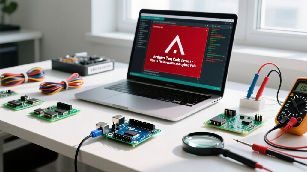
Running a basic arduino test code—like the classic Blink sketch or a simple I2C sensor sweep—should be a seamless experience. However, both beginners and seasoned engineers frequently hit a wall when the IDE throws cryptic compilation errors, upload timeouts, or silent hardware freezes. In 2026, with the widespread adoption of the Arduino IDE 2.x series and newer boards like the Uno R4 and ESP32-S3, the debugging landscape has evolved. This guide bypasses generic advice and dives deep into the exact failure modes, hardware quirks, and software mismatches that derail your test code, providing actionable fixes for each.
1. The 'Port Not Found' or 'Board Not Responding' Upload Error
The most common roadblock when flashing arduino test code is the IDE failing to establish a serial handshake. This is rarely a code issue; it is almost always a physical layer or driver failure.
Charge-Only vs. Data USB Cables
Over 40% of 'dead on arrival' upload failures stem from using a charge-only USB cable. These cables lack the D+ and D- data lines required for serial communication. The Fix: Test your cable by plugging it into a smartphone and a PC. If the PC only charges the phone but does not mount it as a storage device or recognize it in Device Manager, discard the cable. Always keep a dedicated, high-quality data cable (preferably under 1 meter to prevent voltage drop) at your workbench.
CH340G vs. ATmega16U2 Driver Conflicts
If you are using a third-party clone board, it likely uses the CH340G USB-to-serial chip instead of the genuine ATmega16U2. Windows and macOS do not always natively poll the correct drivers for the CH340G, resulting in a missing COM port.
- Genuine Boards: Rely on native CDC/ACM drivers. If missing, reinstall the Arduino IDE and check the 'Install USB Drivers' box during setup.
- Clone Boards: Download the latest signed CH340 drivers directly from the manufacturer (WCH). Avoid third-party driver aggregator sites, which often bundle outdated or malicious software.
Expert Tip: If your COM port appears but the upload fails at 99%, your board's auto-reset circuit is likely broken. You can manually force the bootloader by pressing and releasing the physical RESET button on the board exactly when the IDE console says 'Uploading...'.
2. Compilation Errors in Standard Test Code
Even copy-pasted test code can fail to compile if your local environment violates the strict structural rules of the Arduino build system.
The Folder-Name Mismatch
The Arduino IDE requires the parent folder name to perfectly match the .ino file name. If you download a test code zip file named sensor_test_master_v2, but the file inside is sensor_test.ino, the IDE 2.x compiler will throw a 'file not found' or 'sketch requires a folder' error. The Fix: Rename the parent directory to exactly match the .ino filename, then restart the IDE.
Missing Core Libraries in IDE 2.x
Unlike the legacy 1.8.x IDE, Arduino IDE 2.2+ isolates library dependencies more strictly. If your test code uses Wire.h or SPI.h on an ESP32 or Arduino Uno R4 WiFi, you must ensure the correct board core is installed via the Boards Manager. For the Uno R4 WiFi, you must specifically install the Arduino UNO R4 Boards package; selecting the generic 'Arduino AVR Boards' will result in missing register compilation errors.
3. Microcontroller-Specific Bootloader Strapping Failures
Modern microcontrollers require specific pin states during boot to enter the download mode required for uploading test code. If these 'strapping pins' are tied to external sensors or relays, the upload will fail.
ESP32-S3 and ESP32-C3 Boot Mode
The ESP32-S3 requires GPIO0 to be pulled LOW (connected to GND) during the boot sequence to enter the serial bootloader. If your test code wiring has GPIO0 tied to a pull-up resistor or an active-high sensor, the chip will boot into normal execution mode, ignoring the IDE's upload command.
The Fix: Add a 10kΩ pull-up resistor to GPIO0 for normal operation, but wire a momentary pushbutton between GPIO0 and GND. Hold the button while pressing the EN (Reset) button to force download mode.
Arduino Uno R4 Minima Double-Tap
The Uno R4 Minima uses the Renesas RA4M1 chip, which does not utilize the traditional 1200-bps software reset trick used by the Leonardo or Micro. If the R4 Minima is stuck in a crashing loop, the IDE cannot interrupt it to upload new test code. The Fix: Rapidly double-tap the physical RESET button. The onboard LED will pulse, indicating the chip is in bootloader mode and ready to receive the new sketch.
4. Diagnostic Matrix: Decoding IDE Error Messages
Use this matrix to quickly map your specific IDE error to a hardware or software solution.
| IDE Error Message | Hardware Target | Root Cause | Exact Fix |
|---|---|---|---|
avrdude: stk500_recv(): programmer is not responding |
Arduino Uno R3 / Nano | Wrong board selected, or bootloader corrupted. | Select correct processor (ATmega328P vs Old Bootloader) in Tools menu. Reburn bootloader via ISP if corrupted. |
Serial port 'COM3' already in use |
Any Windows Board | Another program (Cura, 3D slicer, Serial Plotter) is holding the port lock. | Close all background apps. Unplug/replug USB to reset the OS port lock. |
Sketch too big; text section exceeds available space |
Arduino Nano / ATtiny85 | Test code includes heavy libraries (e.g., Adafruit_GFX) exceeding 30KB flash. | Optimize code, use PROGMEM for string literals, or upgrade to an ATmega2560/ESP32. |
Failed to connect to ESP32: Timed out waiting for packet header |
ESP32 DevKit V1 | GPIO0 not pulled low, or insufficient USB current. | Hold BOOT button during upload. Use a powered USB hub providing at least 500mA. |
5. Silent Hardware Failures Masking as Code Errors
Sometimes your arduino test code compiles and uploads perfectly, but the hardware appears dead. The Serial Monitor outputs garbage or nothing at all. Before rewriting your code, check these physical layer issues.
The Brownout Detector (BOD) Trigger
ESP32 and Arduino Nano 33 IoT boards feature a Brownout Detector. If your test code initializes a high-draw peripheral (like a GSM module or a servo motor) directly from the board's 3.3V or 5V pin, the voltage will sag. The BOD will instantly reset the microcontroller to prevent flash corruption, resulting in an endless boot loop that looks like a code crash.
The Fix: Never power inductive loads or high-current radios directly from the MCU's voltage regulator. Use a dedicated buck converter (e.g., LM2596) powered directly from the VIN or RAW pin, and ensure a common ground connection.
I2C Bus Lockups
If your test code uses Wire.begin() to scan for sensors but hangs indefinitely on the Wire.endTransmission() function, your I2C bus is likely missing pull-up resistors or experiencing a capacitance overload. According to SparkFun's serial communication guidelines, I2C requires open-drain configurations with external pull-ups.
The Fix: Add 4.7kΩ pull-up resistors to both SDA and SCL lines. If the bus still hangs, check for a short circuit or a slave device holding the SDA line LOW due to a previous interrupted transaction.
6. The 5-Step 'Nuclear' Diagnostic Routine
When standard troubleshooting fails, follow this systematic diagnostic routine to isolate the fault in your arduino test code setup. For deeper insights into serial debugging, refer to the official Arduino IDE v2 Serial Monitor documentation.
- Enable Verbose Output: Go to File > Preferences and check 'Show verbose output during: upload'. This reveals the exact AVRDude or esptool command failing, highlighting whether the issue is a baud rate mismatch or a chip signature error.
- Perform a Loopback Test: Bridge the TX and RX pins on your board with a jumper wire. Open the Serial Monitor and type characters. If they echo back, your USB-to-Serial chip is functional; the fault lies with the main microcontroller.
- Strip to Bare Metal: Create a new sketch containing only
void setup() { pinMode(LED_BUILTIN, OUTPUT); }andvoid loop() { digitalWrite(LED_BUILTIN, HIGH); }. If this fails to upload, your board's bootloader is corrupted or the MCU is physically dead. - Check the 10µF Capacitor Trick: If your board constantly resets when the Serial Monitor opens (due to the DTR line toggling), place a 10µF electrolytic capacitor between the RESET and GND pins. This absorbs the reset pulse, allowing you to read serial data without interrupting the test code execution.
- Verify Power Injection: Use a multimeter to measure the voltage at the 5V and 3.3V pins while the test code is running. A reading below 4.7V on the 5V pin indicates a failing onboard voltage regulator or a defective USB port on your PC.
Conclusion
Debugging arduino test code is less about rewriting syntax and more about understanding the intersection of software instructions and hardware realities. By systematically eliminating cable faults, driver mismatches, strapping pin conflicts, and power brownouts, you can reduce your troubleshooting time from hours to minutes. Always consult the official Arduino troubleshooting guide for board-specific anomalies, and maintain a disciplined, hardware-first approach to error resolution.