
The Reality of Bluetooth Serial Debugging
When you attempt to control LED Arduino Bluetooth setups, the transition from a hardwired Serial monitor to wireless RF communication introduces a cascade of potential failure points. In 2026, while the ESP32 has largely absorbed the hobbyist market with its native BLE capabilities, discrete modules like the HC-05 (Classic Bluetooth) and HM-10 (Bluetooth Low Energy) remain ubiquitous in legacy educational kits and ultra-low-cost IoT retrofits. However, debugging these modules requires a systematic approach to hardware logic levels, baud rate mismatches, and Serial port contention.
Common Failure Modes in HC-05 and HM-10 Modules
Most makers assume a Bluetooth module is defective when an LED fails to toggle via a smartphone app. In reality, hardware damage or firmware misconfiguration is rarely the culprit. According to the Bluetooth Special Interest Group (SIG), a vast majority of BLE and Classic pairing failures in embedded systems stem from improper power sequencing or logic level violations.
⚠️ CRITICAL WARNING: The 3.3V Logic Level Trap
The HC-05 operates at 3.3V logic. Feeding a 5V signal directly from an Arduino Uno's TX pin into the HC-05's RX pin will degrade the module's internal LDO regulator and eventually fry the UART transceiver. Always use a voltage divider. For a deep dive on logic thresholds, refer to the SparkFun Logic Levels guide.
Step-by-Step Troubleshooting Matrix
Use this diagnostic matrix to isolate the exact layer where your control LED Arduino Bluetooth pipeline is breaking down.
| Symptom | Probable Root Cause | Verified Fix |
|---|---|---|
| Module LED blinks rapidly, won't pair | Module stuck in AT Command Mode | Disconnect EN/KEY pin from 5V; reboot module. |
| Paired, but LED doesn't toggle | Baud rate mismatch in SoftwareSerial | Verify HC-05 data mode baud (default 9600) matches code. |
| Garbage characters in Serial Monitor | Hardware Serial contention | Move BT module to digital pins via SoftwareSerial. |
| App connects, then instantly drops | Insufficient current from Arduino 5V rail | Power HC-05 via dedicated 3.3V/5V buck converter (needs 30mA-50mA spikes). |
| HM-10 invisible to iOS devices | Using Classic BT app instead of BLE app | Use a dedicated BLE scanner (e.g., LightBlue or nRF Connect). |
Wiring & Voltage Divider Verification
To safely control LED Arduino Bluetooth configurations using 5V microcontrollers (like the Uno R3 or Mega2560), you must step down the TX voltage. The RX pin on the HC-05 is strictly 3.3V tolerant.
Calculating the Exact Resistor Values
A standard voltage divider uses two resistors. To drop 5V down to a safe 3.3V, use a 1kΩ resistor (R1) in series with the signal, and a 2kΩ resistor (R2) to ground. The formula V_out = V_in * (R2 / (R1 + R2)) yields 5 * (2000 / 3000) = 3.33V, which is perfectly within the HC-05's tolerance. Ensure your resistors are measured with a multimeter before soldering; a 5% tolerance 2kΩ resistor could read as low as 1900Ω, slightly altering the voltage but remaining safe.
Resolving Serial Monitor & Bluetooth Conflicts
A classic beginner mistake is wiring the Bluetooth module to the Arduino's hardware RX/TX pins (D0 and D1) while simultaneously trying to use the USB Serial Monitor for debugging. The ATmega328P's hardware UART cannot arbitrate between the USB-to-Serial CH340 chip and the Bluetooth module simultaneously.
The solution is utilizing the SoftwareSerial library to bit-bang a secondary UART on digital pins. Here is the optimized, non-blocking approach for 2026 standard practices:
#include <SoftwareSerial.h>
SoftwareSerial BTSerial(10, 11); // RX, TX
const int ledPin = 8;

void setup() {
  Serial.begin(9600); // USB Debug
  BTSerial.begin(9600); // HC-05 Data Mode
  pinMode(ledPin, OUTPUT);
}

void loop() {
  if (BTSerial.available()) {
    char c = BTSerial.read();
    Serial.print("Received: "); Serial.println(c);
    if (c == '1') digitalWrite(ledPin, HIGH);
    if (c == '0') digitalWrite(ledPin, LOW);
  }
}
Advanced AT Command Debugging
If your module refuses to pair or operates at the wrong speed, you must enter AT Command Mode. For the HC-05, this requires holding the onboard button while powering it on, or pulling the EN pin HIGH during boot. The AT mode baud rate is strictly 38400 (unlike the 9600 data mode).
AT+VERSION?- Confirms firmware and communication.AT+UART?- Checks current baud rate (e.g., +UART:9600,0,0).AT+UART=9600,0,0- Forces the baud rate to 9600 to match your Arduino sketch.AT+ROLE?- Verifies if the module is set to Slave (0) or Master (1).
Real-World Component Costs & Sourcing (2026 Perspective)
When building or repairing these circuits, component selection impacts reliability. Generic, unbranded HC-05 clones from bulk marketplaces often feature poorly calibrated crystal oscillators, leading to baud rate drift.
- Genuine HC-05 (Master/Slave): $4.50 - $6.00. Look for the ZS-040 breakout board with a 3.3V LDO and proper EN pin breakout.
- HM-10 (BLE 4.0): $5.50 - $7.50. Essential for iOS compatibility, as Apple restricts Classic Bluetooth SPP profiles.
- ESP32-C3 Dev Board: $3.50 - $4.50. In 2026, many engineers bypass discrete modules entirely, using the ESP32-C3's native BLE 5.0 and integrated USB-Serial for a cheaper, more reliable single-chip solution.
Multimeter Diagnostics for RF Modules
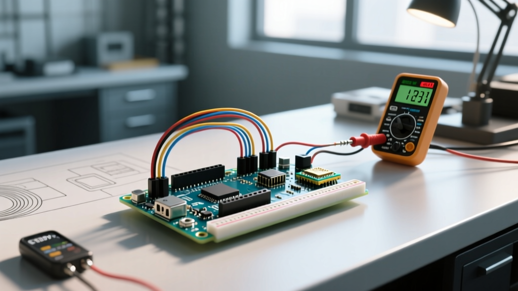
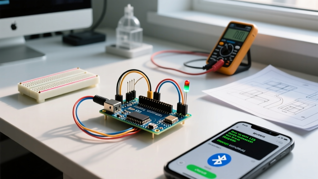
Before blaming the code, verify the physical layer with a digital multimeter (DMM). Set your DMM to DC voltage and probe the VCC and GND pins on the Bluetooth module while it is actively paired and transmitting. A healthy HC-05 should read between 3.28V and 3.35V on its internal logic rail. If you observe the voltage dipping below 3.1V during transmission bursts, your module is experiencing a brownout. This is incredibly common when powering the module directly from the Arduino Uno's 3.3V pin, which is sourced from the onboard FT232 or CH340 USB-Serial chip and is typically limited to 50mA. The fix is to power the HC-05 from the 5V pin, relying on the module's onboard AMS1117-3.3 LDO regulator to handle the step-down, provided the 5V rail has sufficient current headroom.
Antenna Orientation and RF Interference
The trace antenna on the HC-05 and HM-10 is highly directional. If your LED control works perfectly on the workbench but fails when installed in a metal chassis or routed through a wall, antenna polarization is likely the culprit. Ensure the ceramic chip antenna is pointing upward and away from ground planes. Furthermore, keep the module at least 15mm away from the Arduino's crystal oscillator and USB shielding, as the 16MHz clock harmonics can introduce noise floor elevation in the 2.4GHz ISM band, severely degrading packet delivery ratios.
Smartphone App Payload Parsing Errors
Another frequent point of failure when attempting to control LED Arduino Bluetooth devices is the invisible payload data sent by smartphone applications. Popular Android terminals, such as the Kai Morich Serial Bluetooth Terminal, append carriage return and newline characters (
) to every transmission by default. If your Arduino sketch uses a simple Serial.read() loop, it will successfully catch the '1' or '0', but will subsequently read the '
' and '
' characters. If your code includes a fallback else statement that turns the LED off for any unrecognized character, the LED will flicker on for a millisecond and immediately turn off.
To resolve this, implement a data validation check in your C++ sketch to ignore non-printable ASCII control characters:
if (BTSerial.available()) {
  char c = BTSerial.read();
  // Ignore carriage returns and newlines
  if (c == '
' || c == '
') return;
  if (c == '1') digitalWrite(ledPin, HIGH);
  else if (c == '0') digitalWrite(ledPin, LOW);
}
FAQ: Rapid Fire Debugging
Why does my HC-05 LED blink once every 2 seconds?
This indicates the module is successfully paired and in a connected state. If your LED isn't responding, the issue is strictly in your Arduino code's character parsing logic or your smartphone app's payload formatting.
Can I use a 9V battery to power the Arduino and Bluetooth module?
Technically yes, via the Vin pin, but it is highly discouraged. The linear voltage regulator on an Uno R3 will dissipate excess heat, and the current spikes during Bluetooth transmission (up to 50mA) can cause brownouts, resetting the ATmega328P and dropping the connection.