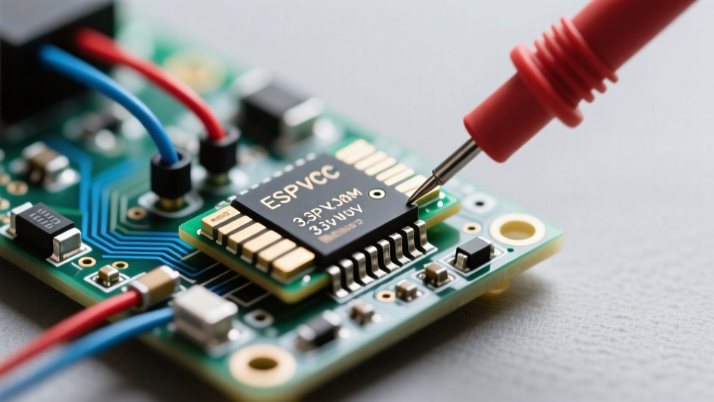
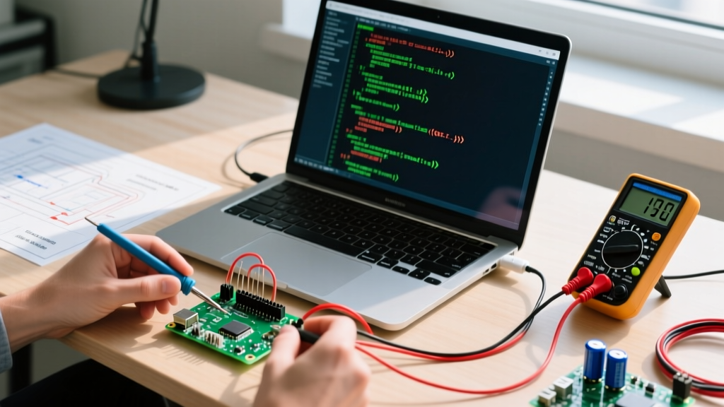
A PWM speed controller varies the average voltage delivered to a DC motor by rapidly switching the power supply on and off at a fixed frequency, controlling speed through the ratio of on-time to off-time (duty cycle). In a real circuit, it changes the effective power delivery and average current without wasting energy as heat, avoiding the massive thermal losses inherent to linear voltage reduction. Makers and technicians commonly confuse PWM frequency (how fast the switching happens, measured in Hertz) with duty cycle (the percentage of time the signal is HIGH), or mistakenly believe PWM reduces the motor's peak torque at lower speeds the way a simple series resistor would. In reality, because the motor's internal inductance smooths the current, the motor experiences near-full supply voltage during the 'on' pulses, maintaining strong torque even at low average speeds.
The Core Mechanics: Duty Cycle vs. Frequency
To understand a PWM speed controller, you must separate the timing of the pulses from the width of the pulses. The duty cycle (D) is the percentage of one period where the signal is active. If you have a 12V supply and set a 40% duty cycle, the motor 'sees' an average of 4.8V. However, the frequency (f) dictates how many of these on/off cycles occur per second.
Choosing the correct frequency is a balancing act between acoustic noise, switching losses in your MOSFETs, and current ripple in the motor windings. If the frequency is too low, the motor will physically vibrate and whine. If it is too high, the MOSFETs in your motor driver will spend too much time in the linear transition region between fully on and fully off, generating excessive heat.
| Frequency Range | Acoustic Noise | MOSFET Switching Losses | Ideal Application |
|---|---|---|---|
| 500 Hz - 1 kHz | High (Audible whine) | Very Low | Hobby servos, slow-moving high-torque winches, basic RC crawlers |
| 4 kHz - 8 kHz | Moderate (Hum) | Low | Standard RC car ESCs, basic conveyor belts, wheelchair motors |
| 15 kHz - 20 kHz | Silent (Ultrasonic) | Moderate to High | 3D printer part-cooling fans, drone ESCs, precision CNC spindles |
| 25 kHz - 50 kHz | Silent | Very High (Requires GaN/FETs) | High-end BLDC controllers, automotive EV traction, medical pumps |
Worked Numeric Example: Calculating RPM and Current Ripple
Let us move from theory to the workbench. Assume you are driving a 12V nominal DC gearmotor with a no-load speed of 3000 RPM and an internal winding inductance (L) of 2 mH and resistance (R) of 1.2 Ω. You are using an ESP32 to drive a TI DRV8871 motor driver at a PWM frequency of 15 kHz.
Target: You need the motor to run at exactly 1200 RPM under no-load conditions.
Step 1: Determine Duty Cycle
Assuming a linear relationship between average voltage and no-load RPM:
Duty Cycle (D) = Target RPM / Max RPM = 1200 / 3000 = 0.40 (40%)
Step 2: Calculate Average Voltage
V_avg = V_supply × D = 12V × 0.40 = 4.8V
Step 3: Calculate Current Ripple
Because the power is pulsing, the current through the motor's inductive windings ramps up during the 'on' time and ramps down during the 'off' time. This is called current ripple ($\Delta I$). Excessive ripple causes heating and torque cogging. The formula for peak-to-peak current ripple in a continuous conduction mode DC motor is:
ΔI = (V_supply × D × (1 - D)) / (f × L)
Plugging in our real-world values:
ΔI = (12 × 0.40 × 0.60) / (15,000 × 0.002)
ΔI = 2.88 / 30 = 0.096 A (96 mA)
A current ripple of 96 mA on a motor drawing roughly 1.5A is excellent (less than 10% ripple). If we had dropped the frequency to 1 kHz, the ripple would spike to 1.44 A, causing the motor to run hot and sound like a buzzer. This mathematical reality is why modern embedded designs push PWM frequencies above the human hearing threshold.
Where You Meet PWM Speed Controllers in Practice
You will encounter PWM speed control across almost every embedded mechatronics project, but the hardware implementation changes drastically based on the current requirements.
- 3D Printer Part Cooling (Low Power, High Frequency): 24V blower fans are driven at 25 kHz. At lower frequencies, the fan blades physically resonate, creating an unbearable whine that ruins the printing environment. Microcontrollers use dedicated high-frequency timer channels for this.
- RC Crawlers and Winches (High Power, Low Frequency): When a winch is pulling a 10 lb rig up a rock, you need maximum torque at near-zero speed. Controllers here often drop to 1 kHz or lower. The high current (30A+) means switching losses at 20 kHz would melt standard TO-220 MOSFETs without massive heatsinks.
- CNC Router Spindle Cooling (Medium Power, Medium Frequency): DC spindle motors (like the 555 or 775 form factors) are typically driven at 4 kHz to 8 kHz using modules like the L298N (for small spindles) or the BTS7960 (for larger 12V/24V setups).
When selecting a hardware module, avoid the classic L298N for anything drawing more than 1.5A continuous. The L298N uses bipolar junction transistors (BJTs) which have a massive voltage drop (up to 2.5V), wasting power as heat. Modern designs use MOSFET-based H-bridges like the BTS7960 (roughly $8.00 for a 43A module) or the DRV8871 (roughly $1.50 for a 3.6A breakout), which offer milliohm-level on-resistance ($R_{DS(on)}$).
Microcontroller Integration: ESP32 LEDC vs. MCPWM
When programming an ESP32 to act as the brain of a PWM speed controller, you have two primary hardware peripherals available. Understanding the difference prevents frustrating debugging sessions later.
The LEDC (LED Control) peripheral is the legacy choice, heavily documented in Arduino environments via the ledcSetup() and ledcWrite() functions. It supports up to 16 channels and is perfectly fine for driving simple DC motors or fans. However, it lacks hardware-level dead-time insertion, which is critical if you are building your own H-bridge from discrete MOSFETs (to prevent shoot-through short circuits).
The MCPWM (Motor Control Pulse Width Modulation) peripheral is the professional choice for motor control. As detailed in the Espressif ESP-IDF MCPWM documentation, this peripheral includes hardware fault handlers, dead-time generation, and synchronization features. If you are building a closed-loop speed controller that reads a quadrature encoder and adjusts the PWM duty cycle on the fly via a PID loop, MCPWM allows you to update the duty cycle synchronously with the PWM cycle, preventing jitter.
analogWrite() wrapper on an ESP32, the default resolution is often 8-bit (0-255). For smooth motor starts, especially with high-inertia loads, configure the LEDC timer to 14-bit resolution (0-16383). This gives you 16,384 discrete speed steps, eliminating the 'jumping' effect you get when moving from a duty cycle of 0 to 1 on an 8-bit scale.
Frequently Asked Questions
Does PWM reduce motor torque at low speeds?
No, not in the way a linear resistor does. Because the motor's inductance filters the pulses into a relatively smooth DC current, the motor winding still experiences the full supply voltage during the 'on' portion of the cycle. This means the magnetic field strength remains high, preserving torque. However, at very low duty cycles (under 10%), the current may become discontinuous, and you will lose some low-end torque unless you implement closed-loop current control.
Why does my motor whine when using a PWM speed controller?
The whine is caused by magnetostriction and physical vibration of the windings at the PWM frequency. If your controller is set to a frequency between 1 kHz and 15 kHz, it falls squarely within the human hearing range. Increase the PWM frequency to at least 18 kHz or 20 kHz to push the acoustic noise into the ultrasonic spectrum, making it completely silent to human ears. Ensure your motor driver MOSFETs are rated for the higher switching speeds to avoid overheating.