
The Hidden Libraries Behind the 'Burn Bootloader' Button
When you click Burn Bootloader in the Arduino IDE, it feels like magic. A progress bar appears, and suddenly your bricked ATmega328P-PU or fresh clone board is resurrected. But as any senior embedded engineer knows, there is no magic—only underlying configuration libraries and execution engines doing the heavy lifting.
In the context of the Arduino ecosystem, a 'library' isn't just a collection of C++ functions like Wire.h or SPI.h. When performing an arduino burn bootloader operation, you are actually invoking two critical configuration libraries: the AVRDUDE Device Definition Library (avrdude.conf) and the Arduino Core Board Library (boards.txt). Understanding how these text-based libraries interact is the difference between a successful flash and a permanently locked microcontroller.
In this deep dive, we will bypass the IDE's GUI abstraction. We will explore the exact hardware requirements, decode the fuse bit configurations, and examine the command-line execution that actually burns the Optiboot bootloader onto your silicon.
The Physical Layer: ISP Programmers and SPI Wiring
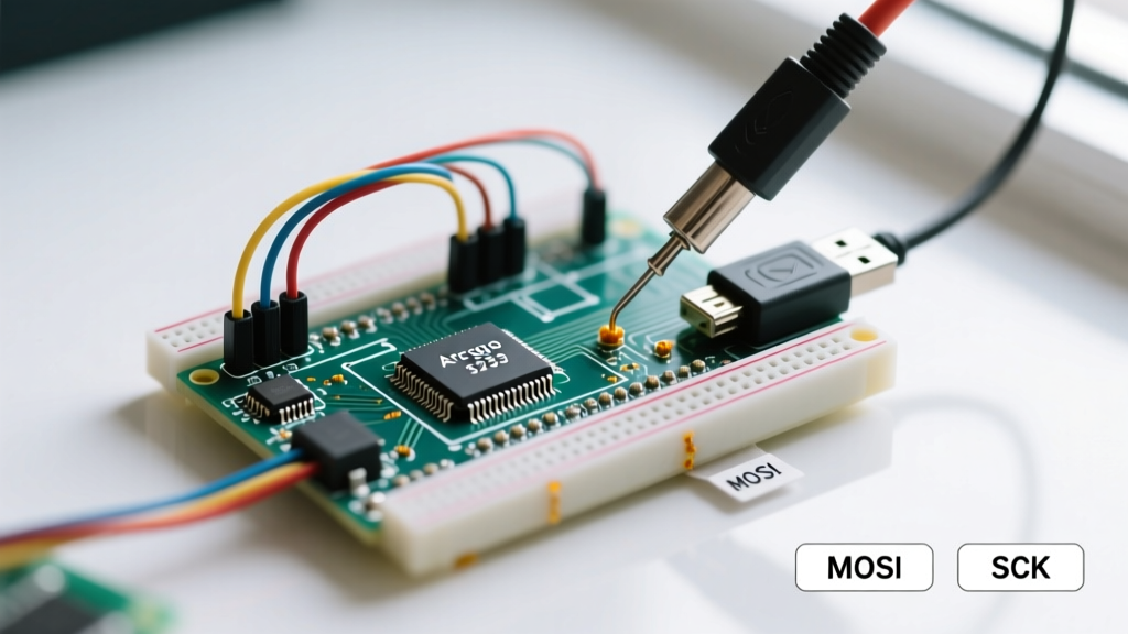
Before the software libraries can do their job, the physical SPI (Serial Peripheral Interface) bus must be correctly established via the ICSP (In-Circuit Serial Programming) header. The bootloader resides in a protected section of the flash memory, which cannot be written to via the standard UART serial connection. It requires direct SPI access to the chip's reset, MOSI, MISO, and SCK pins.
Programmer Selection Matrix (2026 Market)
Choosing the right hardware programmer dictates which configuration library parameters AVRDUDE will use. Here is a breakdown of the most common programmers used today:
| Programmer Model | Approx. Cost | Best Use Case | IDE Menu Selection |
|---|---|---|---|
| USBasp V2.0 (Clone) | $4 - $8 | Budget bulk flashing, DIY labs | USBasp |
| Arduino Uno (as ISP) | $25 (Board) | Quick fixes, no extra hardware | Arduino as ISP |
| Atmel-ICE (ARM/AVR) | $110 - $135 | Pro debugging, PDI/TPI support | Atmel-ICE |
| Pololu AVR Programmer V2 | $22 - $28 | Reliable 3.3V/5V auto-switching | USBtinyISP / Custom |
Expert Warning: If you are using a cheap USBasp clone from AliExpress or Amazon, it often ships with outdated firmware that fails to recognize newer ATmega chips or operates at a fixed 1.5V logic level. Always verify your USBasp firmware version using the avrdude -c usbasp -p m328p -v command before attempting a burn on a 5V target.
ICSP Wiring Standard
Regardless of the programmer, the 6-pin ICSP wiring remains universal. Ensure your ribbon cable is oriented correctly (pin 1 is usually marked with a triangle on the PCB):
- Pin 1 (MISO): Master In, Slave Out (Data from target)
- Pin 2 (VCC): 5V or 3.3V (Power the target if not externally powered)
- Pin 3 (SCK): Serial Clock
- Pin 4 (MOSI): Master Out, Slave In (Data to target)
- Pin 5 (RESET): Target Reset (Crucial for entering programming mode)
- Pin 6 (GND): Ground
Decoding the Board Configuration Library: boards.txt
When you select your target board in the Arduino IDE, the software parses the boards.txt file located within the active hardware core package. This file acts as a board definition library, telling the IDE exactly which fuse bits to write and which bootloader hex file to flash.
Let's dissect the standard arduino:avr:uno configuration block relevant to burning the bootloader:
uno.bootloader.low_fuses=0xFF
uno.bootloader.high_fuses=0xDE
uno.bootloader.extended_fuses=0xFD
uno.bootloader.unlock_bits=0x3F
uno.bootloader.lock_bits=0x0F
uno.bootloader.file=optiboot/optiboot_atmega328.hex
What Do These Fuse Bytes Actually Mean?
Fuse bits are non-volatile memory locations that configure the microcontroller's fundamental hardware behavior. Getting these wrong can 'brick' your chip by disabling the reset pin or selecting a clock source that doesn't exist.
| Fuse Byte | Hex Value | Function & Configuration |
|---|---|---|
| Low Fuse (lfuse) | 0xFF |
Sets clock source to External Crystal (8-16MHz) with 16K CK/14CK + 65ms startup time. |
| High Fuse (hfuse) | 0xDE |
Allocates 512 words (1024 bytes) for the bootloader section; enables SPIEN (Serial Programming Enable). |
| Ext Fuse (efuse) | 0xFD |
Sets Brown-out Detection (BOD) to 2.7V. Prevents code corruption during power sag. |
| Lock Bits | 0x0F |
Locks the bootloader section from being overwritten by the application code via SPM instructions. |
If you are building a custom board running on the internal 8MHz oscillator (eliminating the external 16MHz crystal), you must modify your custom boards.txt library to use lfuse=0xE2 and hfuse=0xDA, and flash the optiboot_atmega328_8mhz.hex variant.
The Execution Engine: AVRDUDE Command Line Deep Dive
The Arduino IDE is essentially a wrapper that generates an AVRDUDE command. AVRDUDE is the open-source command-line utility that actually drives the SPI programmer. By enabling 'Show Verbose Output during Upload' in the IDE preferences, you can see the exact command executed when you click arduino burn bootloader.
Here is the raw command generated for a USBasp targeting an ATmega328P:
avrdude -C avrdude.conf -v -p atmega328p -c usbasp -P usb -e -U lock:w:0x3F:m -U efuse:w:0xFD:m -U hfuse:w:0xDE:m -U lfuse:w:0xFF:m
avrdude -C avrdude.conf -v -p atmega328p -c usbasp -P usb -U flash:w:optiboot_atmega328.hex:i -U lock:w:0x0F:m
Command Flag Breakdown
-C avrdude.conf: Points to the Device Definition Library. This file contains the memory layouts, page sizes, and SPI instruction sets for every supported AVR chip.-p atmega328p: Specifies the target part number from the library.-c usbasp: Defines the programmer type.-e: Performs a chip erase before writing. Critical: You cannot write to the flash memory or change fuse bits without erasing the chip first.-U flash:w:...: Writes the Intel HEX formatted bootloader file to the flash memory.
Troubleshooting Edge Cases and Failure Modes
Even with perfect wiring, the arduino burn bootloader process frequently fails due to edge cases involving clone chips, clock mismatches, and library signature errors. Here is how to resolve the most common roadblocks.
1. The 'Invalid Device Signature' Error
Error: Expected signature for ATmega328P is 1E 95 0F. Double check chip, or use -F to override this check.
The Cause: You are likely using a clone ATmega328P (often manufactured by LGT or other fabs) that returns a different signature, such as 1E 95 16 or 00 00 00. Alternatively, the chip is factory-set to use an external clock, but your board lacks a crystal.
The Fix:
If the signature is 00 00 00, the chip expects an external clock signal. You must temporarily provide an 8MHz-16MHz square wave to the XTAL1 pin (Pin 9 on DIP-28) using a secondary Arduino or a function generator. Once the clock is injected, AVRDUDE can read the signature.
If it's a clone chip with a valid but mismatched signature, you can force the burn by appending the -F flag to the AVRDUDE command, or by editing your local avrdude.conf library to match the clone's signature.
2. The SPI Clock Speed Mismatch
Error: avrdude: warning: cannot set sck period. please check for usbasp firmware update. followed by a verification error.
The Cause: The SPI clock speed of the programmer is too fast for the target microcontroller. By default, USBasp tries to communicate at 1.5MHz. If your target ATmega is running on a 1MHz internal clock (factory default), the SPI bus will fail.
The Fix: You must slow down the programmer's SPI clock. If using a USBasp, short the 'SLOW' jumper pins on the programmer PCB. If using the 'Arduino as ISP' method, you can modify the ArduinoISP.ino sketch to increase the SPI delay, or use a dedicated programmer like the Pololu AVR V2 which handles clock negotiation automatically.
3. Bootloader Verification Failed
Error: verification error, first mismatch at byte 0x7E00
The Cause: The high fuse (hfuse) was not written correctly, meaning the bootloader section size is misconfigured, or the lock bits were applied prematurely, preventing the flash write.
The Fix: Always ensure the command sequence writes the fuses before writing the flash, and applies the final lock bits after the flash verification is complete. The Arduino IDE handles this sequence automatically, but if you are writing custom bash scripts for mass production, sequence order is paramount.
Conclusion: Mastering the Burn
Treating the arduino burn bootloader process as a simple GUI click is a disservice to the complex interplay of hardware SPI protocols and configuration libraries. By understanding the boards.txt fuse definitions and the underlying AVRDUDE execution engine, you transition from a passive user to an embedded systems architect. Whether you are rescuing a bricked DIP-28 chip pulled from an old Uno or flashing 50 custom PCBs with bare ATmega328PB chips, mastering these configuration libraries ensures your hardware foundation is rock solid.
For further reading on standard ISP configurations, refer to the official Arduino as ISP documentation.