
The 2026 Landscape of Arduino Joystick Integration
As we navigate the microcontroller ecosystem in 2026, integrating physical analog controls into digital HID (Human Interface Device) projects remains a cornerstone of DIY electronics. Whether you are building a custom flight simulator yoke, a macro pad, or a robotic rover controller, the Arduino joystick library ecosystem—primarily dominated by the MHeironimus USB HID library and the Adafruit Seesaw I2C drivers—is the standard. However, moving from a breadboard prototype to a reliable, jitter-free input device introduces severe debugging challenges.
This guide bypasses basic wiring tutorials and dives straight into the advanced troubleshooting of analog drift, I2C bus capacitance failures, and Windows HID descriptor caching errors that plague intermediate developers.
Analog Drift and the Flaws of the map() Function
The ubiquitous KY-023 joystick module (typically retailing around $1.50) utilizes dual-gang 10kΩ carbon track potentiometers. Over time, the physical wiper degrades the carbon track, causing the center resting voltage to fluctuate. When read by a 10-bit ADC (0-1023), the theoretical center is 512. A worn KY-023 might output a resting state anywhere between 485 and 535, resulting in severe 'ghost' inputs.
Most beginners attempt to fix this using the native Arduino map() function, which is mathematically flawed for deadzone implementation because it creates a non-linear spike at the deadzone boundary. Instead, you must implement a piecewise software deadzone.
Implementing a Non-Linear Deadzone
Replace your standard mapping logic with a threshold-based clamping function. This ensures that minor physical jitter is completely ignored before the value is passed to the Joystick library.
int applyDeadzone(int raw, int center, int deadzone) {
  int deviation = abs(raw - center);
  if (deviation < deadzone) {
    return center; // Clamp to absolute center
  }
  // Remap the remaining active range to preserve full throw sensitivity
  if (raw > center) {
    return map(raw, center + deadzone, 1023, center, 1023);
  } else {
    return map(raw, 0, center - deadzone, 0, center);
  }
}
Pro-Tip: Set your deadzone variable to at least 15 points for a standard KY-023, and up to 35 points for heavily used modules. Always sample the ADC 16 times and average the result to eliminate 60Hz mains hum interference before applying the deadzone math.
I2C Communication Failures with the Adafruit Seesaw
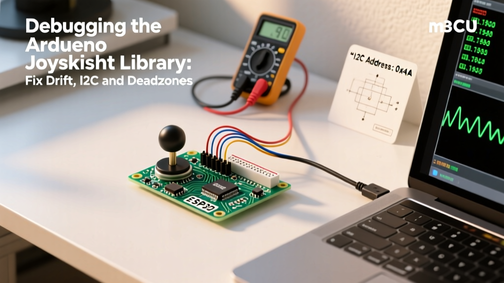
For projects requiring zero ADC jitter and minimal pin usage, developers frequently turn to I2C-based joysticks like the Adafruit Analog Joystick FeatherWing ($12.50), which uses the ATSAMD09 Seesaw chip. When using the Adafruit Seesaw library, the most common failure mode is the I2C bus locking up or returning 0xFFFF on analog reads.
The Pull-Up Resistor Mismatch
The Seesaw breakout boards often lack robust onboard pull-up resistors for high-speed I2C. If you are running an ESP32-S3 or Arduino Nano ESP32 at 3.3V logic, the internal MCU pull-ups (usually 20kΩ to 50kΩ) are far too weak to pull the bus high within the required nanosecond rise-time at 400kHz.
- 5V Logic (Uno R3, Mega2560): Solder external 4.7kΩ pull-up resistors from SDA and SCL to 5V.
- 3.3V Logic (ESP32, Nano 33 IoT): Solder external 2.2kΩ pull-up resistors from SDA and SCL to 3.3V.
According to the official Arduino Wire library documentation, failing to provide adequate pull-up current results in sloping square waves, which the Seesaw chip misinterprets as incomplete clock cycles, triggering a hard bus lock.
Address Collision and Clock Stretching
By default, the Adafruit joystick Seesaw operates at I2C address 0x49. If you are daisy-chaining multiple joysticks, you must use the Seesaw library to rewrite the EEPROM address on each module. Furthermore, if your code uses Wire.setClock(1000000) (1MHz Fast Mode Plus), the ATSAMD09 chip will fail to stretch the clock in time. Cap your I2C bus speed at Wire.setClock(400000) for reliable multi-node polling.
USB HID Descriptor Errors (MHeironimus Library)
When building native USB gamepads using the ATmega32U4 (Arduino Leonardo/Micro) or the ESP32-S2/S3, the MHeironimus Arduino Joystick Library is the undisputed industry standard. However, developers frequently encounter the dreaded "USB Device Not Recognized" error in Windows or a complete failure to enumerate in Linux.
The HID Descriptor Cache Trap
When you change the constructor parameters in your code—for example, adding a Z-axis, changing the button count from 12 to 16, or enabling the rudder axis—the library generates a new USB HID Report Descriptor. Windows aggressively caches USB HID descriptors in its registry. When you plug the updated Arduino back in, Windows applies the old cached descriptor, realizes the byte-lengths don't match the incoming data packets, and immediately disables the device.
Debugging Protocol for HID Cache Errors:
- Open Windows Device Manager.
- Locate the malfunctioning Arduino under "Human Interface Devices" or "Other Devices".
- Right-click and select Uninstall Device.
- CRITICAL: Check the box that says "Attempt to remove the driver for this device".
- Physically unplug the Arduino, reboot the PC, and reconnect.
State Machine Traps in Joystick.begin()
Another fatal coding error occurs when developers place Joystick.begin() inside a conditional loop or call it repeatedly. The USB endpoint will overflow, causing the MCU to crash and reset endlessly (bootlooping). Always initialize the HID stack strictly once in the setup() function, and use Joystick.setXAxis() in the loop(). If you need to dynamically change the button count, you must call Joystick.end(), re-instantiate the object, and call Joystick.begin() again—though this will cause a momentary USB disconnect.
Hardware Edge Cases: VCC Sag and Ground Loops
Software debugging often masks underlying hardware flaws. If your joystick library is outputting erratic values that bypass your deadzone logic, suspect VCC sag. A standard breadboard can introduce a 0.3V to 0.5V drop across its power rails when driving multiple LEDs or servos alongside the joystick.
Because the Arduino ADC measures the potentiometer wiper voltage relative to VCC (when using the default analog reference), a sagging VCC rail actually keeps the ratio stable. However, if you are using an external 3.3V reference for a 5V joystick, or if the ground return path shares a breadboard trace with a high-current motor driver, ground bounce will inject 50mV-100mV of noise directly into the ADC input.
The Fix: Solder a 100nF (0.1µF) ceramic decoupling capacitor directly across the VCC and GND pins on the joystick module itself, not on the Arduino board. This creates a localized high-frequency filter that absorbs EMI before it reaches the wiper.
Master Troubleshooting Matrix
Use this diagnostic table to rapidly isolate your Arduino joystick library faults:
| Symptom | Probable Cause | Debugging Action |
|---|---|---|
| Cursor drifts at rest | Wiper carbon track wear | Implement 15-point software deadzone; average 16 ADC samples |
| I2C Timeout (0x49) | Missing/Weak pull-up resistors | Solder 4.7kΩ to SDA/SCL (5V) or 2.2kΩ (3.3V) |
| Windows "Unknown USB" | HID Descriptor Registry Cache | Delete device in Device Manager with driver removal; reboot |
| Jittery ADC readings | VCC sag / Ground bounce | Measure 5V rail with DMM; solder 100nF cap at joystick VCC/GND |
| Seesaw returns 0xFFFF | I2C Clock Stretching Failure | Reduce Wire clock speed to 400000Hz (400kHz) |
Final Thoughts on Input Latency
Finally, never use delay() in your polling loop. A 10ms delay limits your joystick polling rate to 100Hz, which is unacceptable for modern gaming or precise robotic control. Utilize the micros() function to create a non-blocking polling state machine. By decoupling your ADC reads from your USB HID transmission rates, you can sample the physical joystick at 1,000Hz while transmitting the finalized, deadzone-corrected HID packet at a stable 125Hz or 250Hz, ensuring buttery-smooth input response without overwhelming the USB endpoint buffers.
For deeper insights into I2C bus capacitance limits and advanced Seesaw configurations, refer to the Adafruit Seesaw ATSAMD09 Learning Guide. Mastering these hardware-software intersections is what separates a frustrating prototype from a professional-grade DIY controller.