
Introduction to HD44780 Display Communication
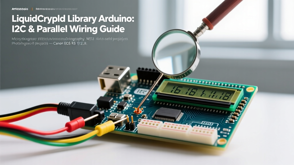
The Hitachi HD44780 controller remains the undisputed industry standard for character LCDs in embedded systems. When working with the LiquidCrystal library Arduino ecosystem, developers typically choose between two primary communication protocols: 4-bit parallel and I2C (Inter-Integrated Circuit). While the native LiquidCrystal library handles parallel communication flawlessly, I2C requires a PCF8574 I/O expander backpack and a derivative library like LiquidCrystal_I2C or the more robust hd44780 library.
This guide provides a definitive, 2026-updated communication setup framework. We will cover exact pinouts, I2C address resolution, timing constraints, and hardware-specific edge cases that frequently trap intermediate developers.
2026 Hardware BOM & Pricing Matrix
Before wiring, ensure you are using reliable hardware. Cheap, unbranded clones often suffer from degraded backlight LEDs and poorly soldered PCF8574 chips. Below is a recommended bill of materials with current market pricing.
| Component | Model / Brand | Protocol | Approx. Price (2026) |
|---|---|---|---|
| Standard 16x2 LCD | Adafruit 181 | Parallel | $9.95 |
| 20x4 Character LCD | HiLetgo / DFRobot | I2C (Pre-soldered) | $11.50 |
| I2C Backpack Adapter | Generic PCF8574 | I2C (DIY Solder) | $2.50 |
| 10K Trimpot (Contrast) | Bourns 3386P | Parallel Req. | $0.85 |
Scenario A: 4-Bit Parallel Communication Setup
The native LiquidCrystal library defaults to 4-bit mode. This is a strategic compromise: it halves the data pin requirement (from 8 to 4) while only marginally increasing the print() execution time. According to Adafruit's LCD engineering guide, 4-bit mode is optimal for ATmega328P-based boards where pin count is at a premium but bus capacitance is not an issue.
Parallel Pin Mapping
The RW (Read/Write) pin is almost universally tied to GND in DIY setups. This forces the display into Write-Only mode, freeing up an Arduino pin and preventing 5V logic backfeeding into the microcontroller.
| LCD Pin | Function | Arduino Uno (ATmega328P) Connection |
|---|---|---|
| 1 (VSS) | Ground | GND |
| 2 (VDD) | Power | 5V |
| 3 (V0) | Contrast | Wiper of 10K Potentiometer |
| 4 (RS) | Register Select | Digital Pin 12 |
| 5 (RW) | Read/Write | GND (Tie Low) |
| 6 (EN) | Enable | Digital Pin 11 |
| 11-14 (D4-D7) | Data Lines | Digital Pins 5, 4, 3, 2 |
| 15 (A) | Backlight Anode | 5V (via 100Ω resistor) |
| 16 (K) | Backlight Cathode | GND |
Parallel Initialization Code
#include <LiquidCrystal.h>
// Initialize: RS, EN, D4, D5, D6, D7
LiquidCrystal lcd(12, 11, 5, 4, 3, 2);

void setup() {
  lcd.begin(16, 2);
  lcd.setCursor(0, 0);
  lcd.print("ElectricalFlux");
  lcd.setCursor(0, 1);
  lcd.print("Parallel Mode");
}

void loop() {
  // Static display
}
Scenario B: I2C Backpack Communication Setup
Using an I2C backpack reduces wiring to just four pins (VCC, GND, SDA, SCL). However, the LiquidCrystal library Arduino search intent often masks a critical misunderstanding: the native LiquidCrystal library does not support I2C. You must use a wrapper library. While LiquidCrystal_I2C by Frank de Brabander is the legacy standard, the hd44780 library by Bill Perry is the 2026 expert recommendation due to its auto-diagnostic addressing and superior execution speed.
The Address Conflict: PCF8574 vs PCF8574A
The most common failure mode in I2C LCD setups is an incorrect hexadecimal address. Backpacks use either the NXP PCF8574 or the PCF8574A I/O expander. They have different base I2C addresses:
- PCF8574: Base address
0x20. With all jumper pads open (A0, A1, A2 HIGH), the address is0x27. - PCF8574A: Base address
0x38. With all jumper pads open, the address is0x3F.
Expert Diagnostic Tip: Never guess the I2C address. Run the standard ArduinoI2CScannersketch. If your scanner returns0x3Fbut your code initializes with0x27, the display will remain completely blank, leading to hours of wasted troubleshooting.
I2C Wiring & Bus Capacitance Rules
As detailed in the official Arduino I2C communication guide, the I2C bus relies on open-drain architecture. If your I2C cable exceeds 30cm, the parasitic capacitance of the wires will degrade the signal rise times, causing ghosting characters or total bus lockups. For runs over 30cm, you must add 4.7kΩ pull-up resistors to both SDA and SCL lines tied to 5V.
I2C Initialization Code
#include <LiquidCrystal_I2C.h>
// Address: 0x27, Columns: 16, Rows: 2
LiquidCrystal_I2C lcd(0x27, 16, 2);

void setup() {
  lcd.init();
  lcd.backlight();
  lcd.setCursor(0, 0);
  lcd.print("ElectricalFlux");
  lcd.setCursor(0, 1);
  lcd.print("I2C Active");
}

void loop() {
  // Static display
}
Performance & Resource Comparison Matrix
Choosing between parallel and I2C depends on your specific microcontroller constraints and refresh rate requirements.
| Metric | 4-Bit Parallel | I2C (PCF8574 Backpack) |
|---|---|---|
| Microcontroller Pins Used | 6 | 2 (Shared bus) |
| Execution Time (16 chars) | ~3.2 ms | ~9.5 ms |
| Wiring Complexity | High (12+ wires) | Low (4 wires) |
| Memory Overhead (Flash) | ~2.1 KB | ~3.8 KB (Includes Wire.h) |
| Multi-Display Support | Difficult (Pin heavy) | Easy (Up to 8 on one bus) |
Advanced Troubleshooting & Edge Cases
Even with correct code, hardware-level anomalies can disrupt communication. Use this checklist to resolve the most persistent edge cases:
- The Contrast Trap (V0 Pin): If the LCD backlight is on but no characters appear (not even black boxes), the contrast voltage is wrong. The V0 pin requires approximately 0.5V to 0.8V. If using a parallel setup, adjust the 10K trimpot. If using an I2C backpack, use a small Phillips screwdriver to turn the brass trimpot on the back of the PCB until the characters resolve.
- Ghosting Characters: If you see faint, duplicate characters trailing your text, your I2C bus is suffering from signal reflection or missing pull-up resistors. Ensure your Arduino's internal pull-ups are active, or add external 4.7kΩ resistors.
- Backlight PWM Interference: If you are using
analogWrite()on a pin adjacent to your LCD data pins (e.g., Pin 11 or 3 on an Uno), the high-frequency PWM signal can capacitively couple into the LCD's Enable (EN) line, causing random character shifts. Move PWM operations to Pins 9 or 10, or use physical shielding. - Logic Level Mismatch: The HD44780 controller operates strictly at 5V logic. If you are using a 3.3V microcontroller (like the ESP32 or Arduino Due), you must use a bidirectional logic level converter on the SDA/SCL or parallel data lines. Feeding 5V I2C signals directly into an ESP32 will eventually degrade the GPIO pins and cause silent I2C bus failures.