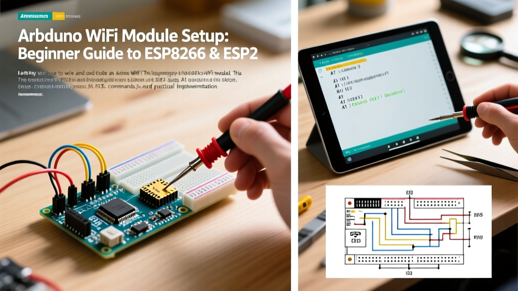

The Evolution of the Arduino WiFi Module in 2026
When beginners search for an Arduino WiFi module, they are usually navigating a transition between two eras of microcontroller networking. Historically, adding WiFi to an Arduino Uno meant purchasing an expensive, proprietary shield. Today, the landscape is dominated by Espressif's silicon. As of 2026, the term 'Arduino WiFi module' almost exclusively refers to either pairing a classic 5V Arduino Uno with an ESP-01S (using AT commands) or graduating to a standalone ESP32/ESP8266 NodeMCU programmed directly via the Arduino IDE.
Understanding which path to take—and how to avoid the common hardware traps that fry beginner setups—is critical. According to the Arduino Official Documentation, mixing 5V logic with 3.3V WiFi modules remains the number one cause of hardware failure in introductory IoT projects. This guide provides exact wiring schematics, voltage division math, and production-ready code to get your first WiFi-connected sensor online.
Hardware Comparison Matrix: Choosing Your Module
Before writing a single line of code, you must select the right hardware. The table below breaks down the three most common modules used by beginners in 2026, including real-world pricing and architectural limits.
| Module | Architecture | Flash Memory | Typical 2026 Price | Logic Level | Best Use Case |
|---|---|---|---|---|---|
| ESP-01S | ESP8266 (Single Core) | 1MB | $2.50 | 3.3V | Adding WiFi to an existing Arduino Uno via Serial |
| NodeMCU V3 | ESP8266 (Single Core) | 4MB | $4.50 | 3.3V | Standalone beginner projects, breadboard friendly |
| ESP32-DevKitC V4 | ESP32 (Dual Core) | 4MB | $5.50 | 3.3V | Advanced IoT, Bluetooth/WiFi combo, native Arduino code |
Note: Always ensure you are buying the ESP-01S (1MB flash) rather than the obsolete original ESP-01 (512KB flash), as modern Arduino IoT libraries require the extra overhead for TLS handshakes.
Wiring the ESP-01S to an Arduino Uno (The 3.3V Trap)
The ESP-01S is a barebones Espressif ESP8266 module that communicates via UART (TX/RX). Because the Arduino Uno operates at 5V and the ESP-01S operates at 3.3V, direct connection will destroy the ESP8266's RX pin. You must use a logic level shifter or a resistor voltage divider.
Step-by-Step Wiring Guide
- Power: Do not use the Uno's 3.3V pin to power the ESP-01S. The Uno's onboard LDO regulator is only rated for ~50mA, while the ESP8266 draws up to 500mA during RF transmission bursts. Use an external 3.3V breadboard power supply or a dedicated AMS1117-3.3 buck converter.
- Decoupling Capacitor: Solder or plug a 100µF to 470µF electrolytic capacitor directly across the ESP-01S VCC and GND pins. This prevents brownout resets during WiFi transmission spikes.
- Enable Pin (CH_PD/EN): Connect the EN pin to 3.3V through a 10kΩ pull-up resistor. Without this, the module will remain in a disabled state.
- TX to RX (Safe): Connect the ESP-01S TX pin directly to the Arduino Uno RX pin (Pin 0 or SoftwareSerial Pin 2). The 3.3V HIGH signal from the ESP is sufficient to trigger the Uno's 5V logic threshold.
- RX to TX (Voltage Divider Required): To step down the Uno's 5V TX to the ESP's 3.3V RX, wire a 1kΩ resistor from the Uno TX to the ESP RX, and a 2kΩ resistor from the ESP RX to GND. This yields exactly 3.33V, which is perfectly safe.
Pro-Tip: The default baud rate for ESP-01S AT firmware is 115200. The Arduino Uno's
SoftwareSeriallibrary cannot reliably read at this speed. Use a USB-to-Serial adapter to send the commandAT+UART_DEF=9600,8,1,0,0once to permanently lower the module's baud rate before using it with the Uno.
Beginner Code: Sending AT Commands via SoftwareSerial
Once wired, the Arduino Uno acts as a passthrough controller, sending AT commands to the ESP-01S. Below is a minimal, non-blocking serial bridge sketch to test your wiring and connect to a local network.
#include <SoftwareSerial.h>

// RX is Pin 2, TX is Pin 3
SoftwareSerial esp8266(2, 3);

void setup() {
  // Initialize hardware serial for PC monitoring
  Serial.begin(9600);
  // Initialize software serial for ESP-01S (pre-configured to 9600)
  esp8266.begin(9600);

  Serial.println("ESP8266 Bridge Ready. Type AT commands.");
  // Test basic communication
  esp8266.println("AT");
}

void loop() {
  // Read from ESP8266 and send to PC
  if (esp8266.available()) {
    Serial.write(esp8266.read());
  }
  // Read from PC and send to ESP8266
  if (Serial.available()) {
    esp8266.write(Serial.read());
  }
}
Open the Arduino IDE Serial Monitor, set the baud rate to 9600, and select 'Both NL & CR'. Type AT+CWMODE=1 to set station mode, followed by AT+CWJAP="YourSSID","YourPassword" to connect. If you receive 'WIFI CONNECTED', your hardware is flawless.
The Modern Alternative: Native ESP32 WiFi Programming
While the Uno + ESP-01S combo is a great learning exercise for UART protocols, the industry standard for beginners in 2026 is to bypass the Uno entirely and program the ESP32 directly using the Arduino Getting Started Guide workflows. The ESP32 features native WiFi MAC/PHY baseband processing, meaning no AT command latency.
To program an ESP32-DevKitC, install the 'esp32' board package via the Arduino IDE Boards Manager. The following code demonstrates a native WPA2 connection and IP retrieval without any external microcontrollers.
#include <WiFi.h>

const char* ssid = "MyNetwork";
const char* password = "MyPassword";

void setup() {
  Serial.begin(115200);
  delay(1000);

  Serial.print("Connecting to WiFi..");
  WiFi.begin(ssid, password);

  // Wait for connection with a timeout safeguard
  int attempts = 0;
  while (WiFi.status() != WL_CONNECTED && attempts < 40) {
    delay(500);
    Serial.print(".");
    attempts++;
  }

  if (WiFi.status() == WL_CONNECTED) {
    Serial.println("\nConnected! IP Address:");
    Serial.println(WiFi.localIP());
  } else {
    Serial.println("\nConnection Failed. Check credentials.");
  }
}

void loop() {
  // Main IoT logic goes here
  delay(1000);
}
Critical Failure Modes and Edge Cases
Even with perfect code, RF environments and power delivery can cause silent failures. Watch for these specific edge cases:
- Brownout Detector Triggered: If your serial monitor spits out
rst:0xc (SW_CPU_RESET)or 'Brownout detector was triggered', your power supply cannot handle the 500mA TX spike. Add a larger bulk capacitor (470µF) or upgrade your 3.3V voltage regulator. - Antenna Detuning: The ESP-01S and NodeMCU use PCB trace antennas. Placing the module flat against a metal breadboard power rail or a grounded copper plane will detune the antenna, dropping your RSSI from -40dBm to -85dBm. Always elevate the module or use an external IPEX/U.FL antenna variant if operating inside a metal enclosure.
- Watchdog Timer (WDT) Resets: In native ESP32 code, if your
loop()function contains a blockingwhile()loop without adelay(1)oryield()call, the RTOS background WiFi tasks will starve, triggering a Guru Meditation Error and resetting the board.
Frequently Asked Questions
Can I use the Arduino Uno's 5V TX pin without a voltage divider if I am in a rush?
No. While some users report the ESP8266 surviving 5V on the RX pin temporarily, the absolute maximum rating for ESP8266 GPIO pins is 3.6V. Prolonged exposure to 5V will degrade the silicon gate oxide, leading to erratic boot loops and eventual permanent failure within weeks.
Does the ESP8266 support modern WPA3 security?
No. The ESP8266 architecture only supports up to WPA2-PSK (AES). If your home router is strictly configured for WPA3-Only, the ESP8266 will fail to associate. You must enable WPA2/WPA3 Transitional Mode on your router, or upgrade to an ESP32-S3 module, which includes the cryptographic accelerators required for WPA3.