
The Evolution of IR Communication in 2026
Infrared (IR) communication remains a cornerstone of hobbyist and industrial electronics due to its simplicity, low cost, and immunity to RF interference. However, the ecosystem surrounding the arduino ir remote control library has undergone significant transformations. If you are following tutorials from a few years ago, you will likely encounter deprecated functions and compilation errors. The shift to the v4.x architecture of the primary IR libraries has fundamentally changed how receivers are instantiated and how decode results are parsed.
This guide provides a comprehensive, modern setup for IR communication, focusing on hardware selection, noise-immune wiring, and optimized code structures for AVR, ESP32, and RP2040 microcontrollers.
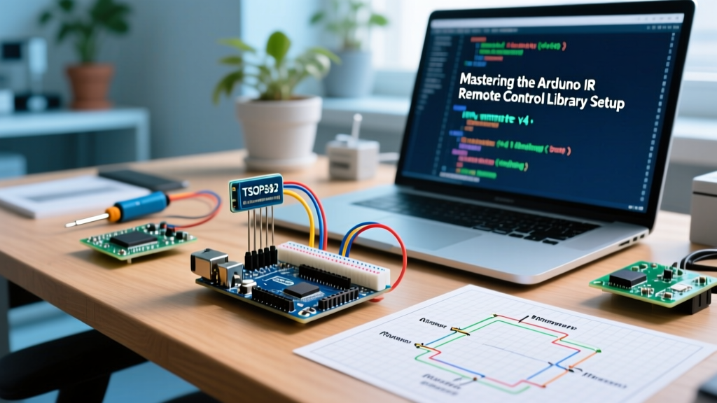
Hardware Selection: TSOP38238 vs. VS1838B
The most common failure mode in DIY IR projects is not bad code, but poor receiver selection. While the generic VS1838B is ubiquitous in cheap starter kits, it suffers from severe Automatic Gain Control (AGC) limitations, frequently triggering false positives under modern LED or CFL room lighting.
| Feature | Vishay TSOP38238 | Generic VS1838B |
|---|---|---|
| Carrier Frequency | 38 kHz | 38 kHz |
| AGC Performance | Excellent (Suppresses continuous noise) | Poor (Prone to saturation) |
| Supply Current | 0.35 mA (Typical) | 1.2 mA (Typical) |
| Unit Cost (2026) | ~$0.85 | ~$0.15 |
| Recommended Use | Production, Battery-powered, Bright rooms | Quick prototyping, Controlled lighting |
For reliable decoding of the arduino ir remote control library signals, we strongly recommend the Vishay TSOP38238. Its internal filter effectively rejects continuous 38kHz noise sources, ensuring your microcontroller only processes valid remote commands.
Wiring for Maximum Noise Immunity
IR receivers are highly sensitive to power supply ripple, especially when powered via the 5V pin of a USB-connected Arduino (which often uses cheap buck converters that introduce high-frequency switching noise).
Expert Wiring Callout:
Never wire a TSOP38238 directly to VCC and GND without decoupling. You must place a 4.7µF to 10µF electrolytic capacitor directly across the VCC and GND pins of the receiver. Additionally, insert a 10Ω to 100Ω series resistor between the Arduino's 5V pin and the receiver's VCC pin. This RC filter eliminates false triggers caused by USB power noise.
Standard Pinout (TSOP38238)
- Pin 1 (OUT): Connect to Arduino Digital Pin 2 (or any interrupt-capable pin).
- Pin 2 (GND): Connect to Arduino GND.
- Pin 3 (Vs): Connect to Arduino 5V (via the 100Ω resistor).
Library Showdown: IRremote vs. IRremoteESP8266
When configuring your development environment, choosing the correct library is critical for memory optimization and protocol support.
- IRremote (by Armin Joachimsthaler): The gold standard for AVR (Uno/Nano/Mega) and RP2040 boards. The current v4.x branch utilizes hardware-specific timers and supports over 50 protocols. View the official IRremote GitHub repository for the latest release notes.
- IRremoteESP8266 (by David Conran): Mandatory if you are using ESP8266 or ESP32 boards. It includes specialized, deeply optimized routines for decoding complex HVAC (Air Conditioner) stateful protocols that the standard IRremote library cannot handle.
Receiver Setup: Navigating the v4.x API
Older tutorials utilize irrecv.decode(&results). This syntax is obsolete. The modern v4.x API encapsulates the results within the receiver object itself, reducing memory overhead and simplifying the main loop.
#include <IRremote.hpp>

const uint8_t IR_RECEIVE_PIN = 2;

void setup() {
  Serial.begin(115200);
  // Initialize the receiver, enabling LED feedback on pin 13 (optional)
  IrReceiver.begin(IR_RECEIVE_PIN, ENABLE_LED_FEEDBACK);
  Serial.println(F("IR Receiver initialized. Waiting for signals..."));
}

void loop() {
  if (IrReceiver.decode()) {
    // Print a summary of the decoded data
    IrReceiver.printIRResultShort(&Serial);

    // Check for specific NEC protocol commands
    if (IrReceiver.decodedIRData.protocol == NEC) {
      if (IrReceiver.decodedIRData.command == 0x16) {
        Serial.println(F("Power Button Pressed!"));
      }
    }

    // CRITICAL: Re-enable the receiver for the next signal
    IrReceiver.resume();
  }
}
The NEC Protocol and the 'Repeat' Edge Case
When working with the arduino ir remote control library, understanding the NEC protocol's repeat mechanism is vital for UI navigation (e.g., holding down a volume button). When a button is held, the remote sends the initial 32-bit frame (9ms pulse, 4.5ms space), followed by repeat frames (9ms pulse, 2.25ms space) every 108ms.
In the v4.x API, the library flags this automatically. You must check the flags property:
if (IrReceiver.decodedIRData.flags & IRDATA_FLAGS_IS_REPEAT) {
  Serial.println(F("Button is being held down (Repeat frame)."));
}
Failing to handle this flag results in dropped inputs during long-press events, a common frustration detailed in Adafruit's comprehensive IR sensor guides.
Transmitter Setup: Pushing Beyond 2 Meters
The standard Arduino IR transmitter circuits shown in basic guides connect an IR LED directly to a digital pin via a 100Ω resistor. This limits the LED current to roughly 20mA, yielding a pathetic range of 1 to 2 meters.
To achieve room-wide coverage (5 to 10 meters), you must drive the IR LED with short, high-current pulses (100mA - 500mA). Microcontroller GPIO pins cannot supply this current.
High-Power Transistor Driver Circuit
- Use a 940nm High-Power IR LED (e.g., TSAL6200).
- Connect the LED's anode to 5V via a 10Ω, 1W resistor (this limits peak current to ~300mA, well within the LED's pulsed rating).
- Connect the LED's cathode to the Collector of an NPN transistor (2N2222 or BC547).
- Connect the Emitter to GND.
- Connect the Base to your Arduino PWM pin (e.g., Pin 3) via a 1kΩ resistor.
The library automatically handles the 38kHz PWM modulation on the hardware timer; the transistor simply acts as a high-speed switch to deliver the necessary current bursts.
Troubleshooting Matrix
When your arduino ir remote control library implementation fails, use this diagnostic matrix to identify the root cause quickly.
| Symptom | Probable Root Cause | Technical Fix |
|---|---|---|
| Random, continuous decoding of unknown hex codes | Power supply noise or CFL/LED ambient light saturation. | Add 4.7µF decoupling capacitor and 100Ω series resistor to receiver VCC. Switch to TSOP38238. |
Code compiles but decode() always returns false |
Timer conflict with another library (e.g., Servo or SoftwareSerial). | Change the IR receiver pin. IRremote uses specific hardware timers tied to specific pins depending on the MCU. |
| Transmitter only works within 10 cm | Insufficient LED drive current; GPIO limit reached. | Implement the NPN transistor driver circuit detailed above to push 300mA pulsed current. |
| Decoder reads protocol as 'UNKNOWN' consistently | Using a 36kHz receiver for a 38kHz remote, or vice versa. | Verify remote carrier frequency using an oscilloscope or logic analyzer, and match the receiver module accordingly. |
Summary
Mastering the arduino ir remote control library requires moving beyond copy-pasted legacy code and cheap starter-kit components. By investing in high-AGC receivers like the TSOP38238, implementing proper RC decoupling, adopting the modern v4.x object-oriented API, and utilizing transistor-driven transmitter circuits, you can build commercial-grade IR communication interfaces that are robust, responsive, and immune to environmental noise.