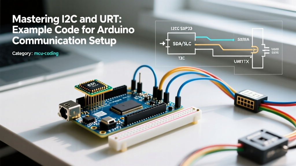

Introduction to Microcontroller Communication Protocols
When building embedded systems in 2026, robust communication between your microcontroller and peripheral sensors is non-negotiable. Whether you are logging environmental data or controlling robotic actuators, understanding the physical and logical layers of serial protocols is critical. This guide provides a production-ready example code for Arduino that bridges I2C sensor polling with UART serial debugging, specifically targeting the ubiquitous ATmega328P and ATmega2560 architectures.
UART Setup: Hardware vs. Software Serial
Universal Asynchronous Receiver-Transmitter (UART) remains the backbone of MCU debugging. While the Arduino Uno (ATmega328P) possesses only one hardware UART (pins 0 and 1), the Arduino Mega 2560 features four. If you are constrained to an Uno and need a secondary UART for a GPS module or Bluetooth HC-05, you must rely on the SoftwareSerial library. However, SoftwareSerial is not without severe limitations:
- CPU Blocking: It disables interrupts during byte transmission, causing missed I2C or timer events.
- Baud Rate Ceilings: Reliable communication tops out at 57600 baud on a 16MHz crystal. At 115200 baud, the bit-banging timing drift exceeds the standard +/- 2% receiver tolerance.
- Half-Duplex Constraint: You cannot transmit and receive simultaneously.
For the example code for Arduino provided below, we utilize the hardware UART at 115200 baud. At a 16MHz clock speed, the UBRR (USART Baud Rate Register) calculation yields a -3.5% error margin for 115200 baud, which is safely within the acceptable threshold for modern USB-to-Serial FTDI chips like the FT232RL.
I2C Bus Configuration and Pull-Up Resistor Math
The Inter-Integrated Circuit (I2C) protocol uses a multi-master, multi-slave architecture over just two wires: SDA (data) and SCL (clock). A common pitfall for beginners is omitting pull-up resistors, leading to floating logic levels and bus lockups. According to the SparkFun I2C Tutorial, the I2C specification mandates open-drain outputs, meaning devices can only pull the line LOW; the resistors are required to pull the line HIGH.
Calculating the Correct Pull-Up Value
Selecting the right resistor depends on the bus capacitance (Cb) and the desired clock speed. The standard formula for the minimum resistor value is Rp(min) = (Vcc - Vol(max)) / Iol, where Vol(max) is typically 0.4V and Iol is 3mA. For a 5V system, this yields a hard minimum of roughly 1.5kΩ. However, higher speeds require lower resistance to charge the bus capacitance faster.
| I2C Speed Mode | Clock Frequency | Recommended Pull-Up (5V) | Max Bus Capacitance |
|---|---|---|---|
| Standard | 100 kHz | 4.7 kΩ | 400 pF |
| Fast | 400 kHz | 2.2 kΩ | 400 pF |
| Fast Plus | 1 MHz | 1.0 kΩ | 550 pF |
For our implementation, we will interface with the Bosch BME280 environmental sensor. The Arduino Wire Library Documentation handles the low-level I2C bit-banging and clock stretching, but you must ensure the sensor's SDO pin is tied to GND to set the I2C address to 0x76 (or VCC for 0x77).
The Core Implementation: Example Code for Arduino
Below is the complete, heavily commented C++ implementation. This sketch initializes the Wire library, configures the BME280 sensor, and streams formatted telemetry over the hardware UART. Ensure you have the Adafruit_BME280_Library and Adafruit_Unified_Sensor installed via the Arduino IDE 2.3.x Library Manager.
#include <Wire.h>
#include <Adafruit_Sensor.h>
#include <Adafruit_BME280.h>

// Define I2C parameters
#define SEALEVELPRESSURE_HPA (1013.25)
#define BME_I2C_ADDR 0x76

Adafruit_BME280 bme;
unsigned long lastTransmission = 0;
const unsigned long transmissionInterval = 2000; // 2 seconds

void setup() {
  // Initialize Hardware UART at 115200 baud
  Serial.begin(115200);
  while(!Serial) {
    ; // Wait for serial port to connect. Needed for native USB boards
  }

  Serial.println(F("BME280 I2C + UART Communication Setup"));

  // Initialize I2C Bus (Wire)
  Wire.begin();
  Wire.setClock(400000); // Set I2C to Fast Mode (400kHz)

  // Initialize BME280 Sensor
  bool status = bme.begin(BME_I2C_ADDR, &Wire);
  if (!status) {
    Serial.println(F("CRITICAL: Could not find BME280 sensor. Check I2C wiring and pull-ups!"));
    while (1) {
      delay(100); // Halt execution on failure
    }
  }

  Serial.println(F("Sensor initialized successfully. Streaming data..."));
}

void loop() {
  unsigned long currentMillis = millis();

  // Non-blocking delay using millis()
  if (currentMillis - lastTransmission >= transmissionInterval) {
    lastTransmission = currentMillis;
    transmitTelemetry();
  }
}

void transmitTelemetry() {
  // Format data as CSV for easy parsing in Python or serial loggers
  Serial.print(bme.readTemperature());
  Serial.print(",");
  Serial.print(bme.readPressure() / 100.0F);
  Serial.print(",");
  Serial.print(bme.readAltitude(SEALEVELPRESSURE_HPA));
  Serial.print(",");
  Serial.println(bme.readHumidity());
}
Code Breakdown and Edge Case Handling
- Non-Blocking Timing: Notice the use of
millis()instead ofdelay(). In complex communication setups, blocking delays will cause UART buffer overflows and I2C timeout errors. Themillis()rollover edge case is handled correctly by subtracting the previous timestamp from the current one, leveraging unsigned integer overflow arithmetic. - I2C Clock Speed: We explicitly call
Wire.setClock(400000);. By default, the Arduino Wire library initializes at 100kHz. Pushing to 400kHz requires the 2.2kΩ pull-up resistors mentioned in our table to ensure the SDA/SCL rise times meet the I2C specification of 300ns. - Memory Optimization: The
F()macro is used in allSerial.println()string literals. This forces the compiler to store the strings in flash memory (PROGMEM) rather than consuming the ATmega328P's limited 2KB SRAM.
Hardware Debugging: When the Code Fails
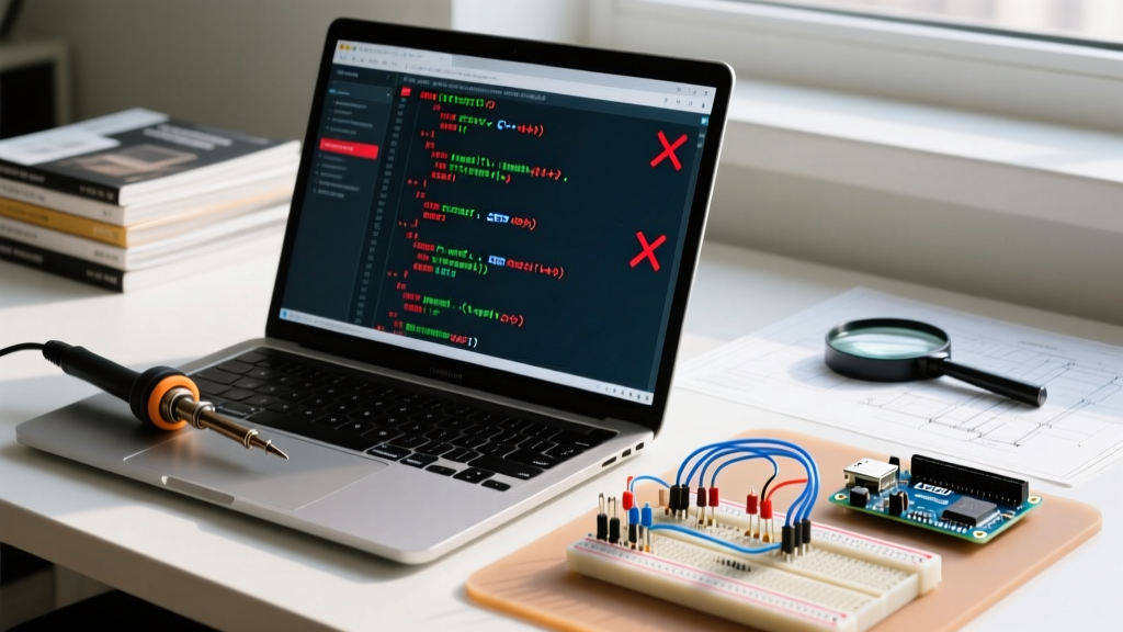
Even with perfect example code for Arduino, hardware anomalies will occur. If your serial monitor outputs "CRITICAL: Could not find BME280 sensor", do not blindly rewrite the code. Diagnose the physical layer.
Using a Logic Analyzer
Connect a logic analyzer (such as the DreamSourceLab DSLogic Plus or a Saleae Logic 8) to the SDA and SCL lines. Set the trigger to the falling edge of SCL. If you see the Arduino transmitting the address byte (0xEC for write, 0xED for read) but the 9th clock cycle (the ACK bit) remains HIGH, the slave is not acknowledging. This confirms an addressing error, a missing pull-up resistor, or a dead sensor.
Pro-Tip for 2026: Modern open-source tools like PulseView (sigrok) now include advanced I2C packet decoders that can automatically flag NACKs and bus contention errors, saving hours of manual hex decoding.
Common Failure Modes
- Bus Lockup: If the Arduino resets while the BME280 is transmitting a '0' bit, the sensor will hold SDA low waiting for the next clock pulse. The Arduino's I2C hardware will refuse to initiate a new start condition. Fix: Implement a bus recovery routine that toggles the SCL pin manually 9 times to force the slave to release the line.
- Ground Loops: When powering the sensor from a separate 3.3V LDO regulator, ensure the GND of the regulator is tied directly to the Arduino GND at a single star point. A ground potential difference of just 0.5V can corrupt the I2C logic thresholds.
Conclusion
Mastering microcontroller communication requires moving beyond simple copy-paste tutorials. By understanding the electrical constraints of I2C pull-ups, the timing realities of UART baud rates, and implementing non-blocking software architectures, you ensure your embedded projects are resilient in real-world environments. Use this example code for Arduino as a foundational template, and always verify your physical layer with a logic analyzer when the data stream stops flowing.