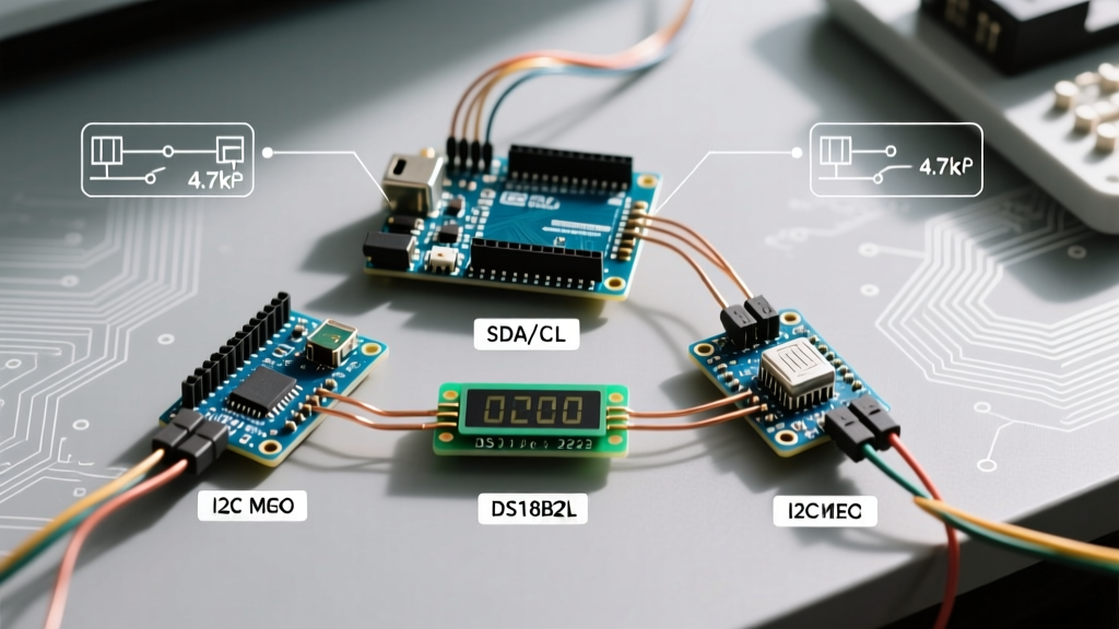

The Definitive Guide to I2C Arduino Pins
Inter-Integrated Circuit (I2C) remains the backbone of microcontroller sensor networks in 2026. Whether you are building a weather station or a multi-node robotics array, mastering I2C Arduino pins is non-negotiable. While the protocol is elegantly simple—requiring only two wires—confusion frequently arises when migrating between board form factors, dealing with mixed logic levels, or debugging silent bus failures.
This tutorial bypasses generic overviews. We will map the exact I2C pins across the modern Arduino ecosystem, dissect the hardware requirements for a stable bus, and walk through production-ready C++ code for bus scanning and sensor polling.
I2C Arduino Pin Mapping Matrix
Unlike SPI, which can be remapped to almost any digital pin via software bit-banging, hardware I2C is tied to specific internal peripherals. The transition from the classic ATmega328P (Uno R3) to the Renesas RA4M1 (Uno R4) shifted underlying silicon architectures, though header layouts largely remained consistent for shield compatibility.
| Arduino Board | SDA Pin (Data) | SCL Pin (Clock) | Native Logic Level | Max Hardware Speed |
|---|---|---|---|---|
| Uno R3 / Nano (Classic) | A4 (Dedicated Header) | A5 (Dedicated Header) | 5.0V | 400 kHz |
| Uno R4 Minima / WiFi | Dedicated Header Only | Dedicated Header Only | 5.0V (3.3V on ESP32-S3) | 1 MHz (FSP I2C) |
| Mega 2560 | 20 (Dedicated Header) | 21 (Dedicated Header) | 5.0V | 400 kHz |
| Nano 33 IoT / BLE | A4 (Dedicated Header) | A5 (Dedicated Header) | 3.3V | 1 MHz (SAMD21) |
Hardware Note for Uno R4 Users: On the Uno R4 series, the SDA and SCL lines are routed directly to the dedicated I2C header near the USB port. Attempting to use analog pins A4/A5 for hardware I2C on the R4 will fail, as those pins are mapped to different ADC channels on the Renesas chip. Always use the dedicated header pins.
Hardware Wiring Rules & Pull-Up Resistor Physics
I2C is an open-drain protocol. Devices pull the line LOW, but they cannot drive it HIGH. This means pull-up resistors are mandatory. Without them, your I2C Arduino pins will float, resulting in erratic readings or complete bus lockups.
Calculating Pull-Up Resistor Values
According to the official NXP I2C-bus specification (UM10204), the bus capacitance must not exceed 400 pF. The resistor value dictates the rise time of the signal.
- 100 kHz (Standard Mode): Use 4.7kΩ resistors. This is the default for most 5V Arduino setups.
- 400 kHz (Fast Mode): Use 2.2kΩ to 3.3kΩ resistors to ensure the signal rises fast enough before the next clock edge.
- Multiple Modules: Every I2C breakout board (like Adafruit's BME280 or SparkFun's MPU6050) usually includes 4.7kΩ pull-ups enabled by default via a solder jumper. If you connect three modules, you are placing three 4.7kΩ resistors in parallel, resulting in ~1.56kΩ. This is generally acceptable but approaches the minimum sink current limit of standard I2C buffers.
Logic Level Shifting (3.3V vs 5V)
Connecting a 3.3V sensor (like a modern Qwiic/Stemma QT module) directly to the 5V I2C Arduino pins of an Uno R3 will degrade the sensor's lifespan. Use a bidirectional logic level converter based on the BSS138 N-Channel MOSFET. These modules cost roughly $1.50 in 2026 and safely isolate the voltage domains while maintaining the open-drain pull-up architecture.
Code Walkthrough 1: The I2C Bus Scanner
Before writing sensor-specific code, always verify physical connections. The Arduino Wire Library provides the tools to interrogate the bus. This scanner iterates through all 127 possible I2C addresses and reports which devices acknowledge their presence.
#include <Wire.h>

void setup() {
  Serial.begin(115200);
  // Wait for serial port to connect. Necessary for native USB boards (Nano 33 IoT, Uno R4)
  while (!Serial) { delay(10); }

  Serial.println("\nI2C Bus Scanner Initialized");
  Wire.begin(); // Join I2C bus as Master
  // Wire.setClock(400000); // Uncomment to force 400kHz Fast Mode
}

void loop() {
  byte error, address;
  int nDevices = 0;

  Serial.println("Scanning...");

  for (address = 1; address < 127; address++ ) {
    Wire.beginTransmission(address);
    error = Wire.endTransmission();

    if (error == 0) {
      Serial.print("I2C device found at address 0x");
      if (address < 16) Serial.print("0");
      Serial.print(address, HEX);
      Serial.println("  !");
      nDevices++;
    }
    else if (error == 4) {
      Serial.print("Unknown error at address 0x");
      if (address < 16) Serial.print("0");
      Serial.println(address, HEX);
    }
  }

  if (nDevices == 0)
    Serial.println("No I2C devices found. Check wiring and pull-ups!\n");
  else
    Serial.println("Scan complete.\n");

  delay(5000); // Wait 5 seconds before next scan
}
Decoding Wire.endTransmission() Errors
Understanding the return value of Wire.endTransmission() is critical for debugging:
- 0: Success. Device acknowledged.
- 1: Data too long to fit in transmit buffer.
- 2: Received NACK on transmit of address. (Device is missing, or SDA/SCL are swapped).
- 3: Received NACK on transmit of data.
- 4: Other error (Bus collision or hardware fault).
- 5: Timeout (Specific to newer Wire implementations like SAMD/ESP32).
Code Walkthrough 2: Polling a BME280 Environmental Sensor
Let's move from scanning to data extraction. The Bosch BME280 is an industry-standard sensor for temperature, humidity, and barometric pressure. Generic breakout boards cost around $3.50–$5.00, while premium Adafruit versions retail near $15.00. Note that BME280 modules often ship with the I2C address configured to 0x76 via a physical SDO pad, though the default in many libraries is 0x77.
#include <Wire.h>
#include <Adafruit_Sensor.h>
#include <Adafruit_BME280.h>

#define SEALEVELPRESSURE_HPA (1013.25)

Adafruit_BME280 bme;

void setup() {
  Serial.begin(115200);
  while(!Serial);

  // Initialize I2C on default pins
  Wire.begin();

  // Explicitly pass the I2C address.
  // Use 0x76 for most generic modules, 0x77 for Adafruit.
  bool status = bme.begin(0x76, &Wire);

  if (!status) {
    Serial.println("Could not find a valid BME280 sensor, check wiring or I2C address!");
    while (1); // Halt execution
  }

  // Configure IIR filter and oversampling for stable readings
  bme.setSampling(Adafruit_BME280::MODE_FORCED,
                    Adafruit_BME280::SAMPLING_X16, // Temp
                    Adafruit_BME280::SAMPLING_X16, // Pressure
                    Adafruit_BME280::SAMPLING_X16, // Humidity
                    Adafruit_BME280::FILTER_X16,
                    Adafruit_BME280::STANDBY_MS_0_5);
}

void loop() {
  // Must call takeForcedMeasurement() every time we want new data in forced mode
  bme.takeForcedMeasurement();

  Serial.print("Temperature = ");
  Serial.print(bme.readTemperature());
  Serial.println(" *C");

  Serial.print("Pressure = ");
  Serial.print(bme.readPressure() / 100.0F);
  Serial.println(" hPa");

  Serial.print("Humidity = ");
  Serial.print(bme.readHumidity());
  Serial.println(" %");

  Serial.println("------------------------");
  delay(2000);
}
Advanced Troubleshooting & Edge Cases
Even with perfect code, hardware physics can derail an I2C bus. Here are the most common failure modes encountered in the field, as documented in advanced embedded communication guides.
1. Swapped SDA and SCL Lines
Unlike UART (TX/RX), swapping SDA and SCL will not physically damage your Arduino or the sensor. However, the bus will completely lock up. The master will generate clock pulses on the SDA line, which the slave ignores, and the master will listen for data on the SCL line, hearing nothing. Fix: Swap the wires. A reboot of the Arduino is often required to clear the internal I2C state machine after a swap.
2. Clock Stretching Timeouts
Some sensors (like certain LiPo fuel gauges or complex OLED displays) use 'clock stretching'—holding the SCL line LOW to force the master to wait while they process data. The standard Wire.h library on AVR boards (Uno R3, Mega) has a hardcoded timeout of roughly 1 second. If a 3.3V sensor stretches the clock but lacks the drive strength to pull the 5V bus fully LOW due to improper level shifting, the master will read a floating voltage and crash. Fix: Ensure MOSFET-based level shifters are used, not simple resistor dividers.
3. Bus Capacitance Overload
If you are running I2C cables longer than 30cm, or daisy-chaining more than 5 modules, the parasitic capacitance of the wires will exceed the 400pF limit. The square wave will degrade into a sawtooth wave, causing bit errors. Fix: Use an active I2C bus extender like the PCA9615 or PCA9600, which converts the I2C signal to a differential pair for long-distance runs.
Summary
Mastering I2C Arduino pins requires looking beyond the basic Wire.begin() command. By respecting the physical pin mappings of modern boards like the Uno R4, calculating pull-up resistances based on bus capacitance, and utilizing robust scanning code, you can build sensor networks that operate reliably in real-world conditions.