
The DY-SV5W Module: Beyond Basic IO Triggers
The DY-SV5W remains one of the most reliable, low-cost audio playback modules in the DIY electronics space. As of 2026, you can typically source these boards for around $4.50 to $6.00. While many beginner tutorials rely on the module's IO trigger pins (pulsing a pin to play a specific track), this approach is severely limited. It restricts you to 20 predefined tracks and offers no volume control, pause/resume functionality, or playback state feedback.
To unlock the full potential of the module, we must use its UART (Universal Asynchronous Receiver-Transmitter) serial interface. This guide provides a comprehensive, production-ready approach to DY-SV5W Arduino code, covering hardware logic-level translation, the hexadecimal command protocol, dynamic checksum generation, and the notorious SD card indexing traps that plague 90% of first-time implementations.
Hardware Wiring & Logic Level Translation
The DY-SV5W operates natively at 5V logic. However, modern microcontrollers like the ESP32 or Arduino Uno R4 Minima operate at 3.3V. Feeding 5V from the module's TX pin into a 3.3V MCU pin can degrade or destroy the MCU's GPIO over time.
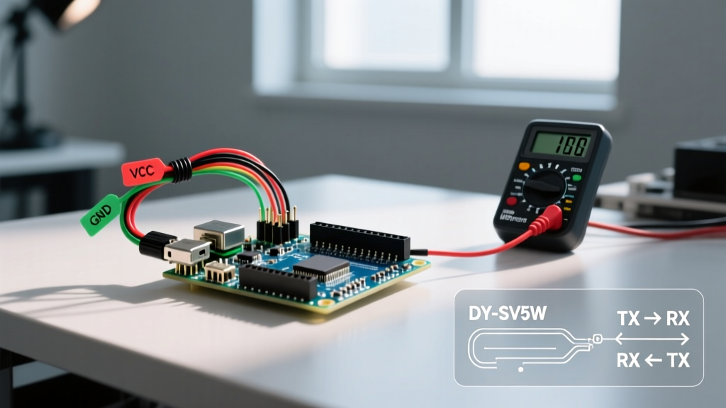
| Module Pin | Arduino Uno (5V) | ESP32 / 3.3V MCU | Engineering Notes |
|---|---|---|---|
| VCC | 5V | 5V | Requires up to 200mA during loud audio peaks. |
| GND | GND | GND | Ensure a common ground plane to avoid serial noise. |
| TX | Pin 10 (RX) | GPIO 16 (RX) | Direct connection safe for 5V MCUs only. |
| RX | Pin 11 (TX) | GPIO 17 (TX) | Use a 1KΩ series resistor to prevent signal ringing. |
Expert Tip: Even when using a 5V Arduino, placing a 1KΩ resistor in series with the module's RX line is highly recommended. Long jumper wires act as antennas and can cause voltage overshoot (ringing) that triggers phantom commands on the DY-SV5W's UART buffer.
Decoding the UART Hex Protocol
The DY-SV5W uses a strict 6-byte hexadecimal command frame. Unlike some MP3 modules that use ASCII strings, this module requires raw byte arrays. According to standard Arduino serial communication principles, we must send these bytes sequentially without delays between them.
The frame structure is as follows:
- Header: Always
0xAA - Command Byte: Defines the action (e.g.,
0x02for Play by Index,0x13for Volume Set) - Parameters (3 Bytes): Data payload (e.g., track number or volume level)
- Checksum: The sum of the previous 5 bytes, truncated to 8 bits (modulo 256).
Most online examples hardcode these 6-byte arrays. This is bad practice. If you want to change the volume dynamically via a potentiometer, hardcoding fails. Instead, we will write a dynamic C++ helper function that calculates the checksum on the fly.
Production-Ready Arduino Code
The following code utilizes the SoftwareSerial library to free up the hardware serial port for debugging. For deeper library mechanics, refer to the official Arduino SoftwareSerial documentation.
#include <SoftwareSerial.h>

// Define SoftwareSerial on pins 10 (RX) and 11 (TX)
SoftwareSerial dySerial(10, 11);

void setup() {
  Serial.begin(9600); // Hardware serial for debugging
  dySerial.begin(9600); // DY-SV5W default baud rate

  delay(500); // Wait for module to initialize

  // Set Volume to 15 (Range is 0-30)
  sendCommand(0x13, 0x00, 0x0F, 0x00);
  Serial.println("Volume set to 15");

  delay(1000);

  // Play Track 1
  sendCommand(0x02, 0x00, 0x00, 0x01);
  Serial.println("Playing Track 1");
}

void loop() {
  // Main logic here
}

// Dynamic Checksum Command Sender
void sendCommand(uint8_t cmd, uint8_t param1, uint8_t param2, uint8_t param3) {
  uint8_t buffer[6];
  buffer[0] = 0xAA;      // Header
  buffer[1] = cmd;       // Command
  buffer[2] = param1;    // Param 1
  buffer[3] = param2;    // Param 2
  buffer[4] = param3;    // Param 3

  // Calculate Checksum (Sum of bytes 0-4, truncated to 8-bit)
  buffer[5] = buffer[0] + buffer[1] + buffer[2] + buffer[3] + buffer[4];

  dySerial.write(buffer, 6);
}
Essential Command Cheat Sheet
- Play by Index:
cmd = 0x02,param3 = Track Number - Set Volume:
cmd = 0x13,param3 = Volume (0x00 to 0x1E) - Pause/Resume:
cmd = 0x0A,params = 0x00 - Stop Playback:
cmd = 0x0B,params = 0x00 - Play All (Loop):
cmd = 0x05,params = 0x00
The SD Card Indexing Trap (And How to Avoid It)
The most common failure mode when deploying DY-SV5W Arduino code is the module playing the wrong audio file. You send the command for Track 3, but it plays a random sound effect. This is not a bug in your code; it is a quirk of the module's rudimentary FAT file system reader.
The DY-SV5W does not read files alphabetically or by their filename. It reads them in the exact order they were written to the FAT allocation table. Furthermore, hidden system files created by macOS (like .Spotlight-V100 or .fseventsd) or Windows (like System Volume Information) are counted as audio tracks by the module, completely shifting your index mapping.
The Bulletproof SD Preparation Workflow
- Format Correctly: Do not use your OS's native formatter. Download the official SD Memory Card Formatter from the SD Association. Format the card as FAT32 with a 32KB allocation unit size.
- Purge Hidden Files: If using a Mac, run
dot_clean /Volumes/YOUR_SD_CARDin the terminal to strip hidden AppleDouble files. - Sequential Copying: Copy your MP3/WAV files to the SD card one by one, in the exact numerical order you want them indexed. Do not drag and drop a folder containing 50 files all at once, as the OS will write them to the FAT table in a random, parallelized order.
- Naming Convention: Name files sequentially without gaps:
001.mp3,002.mp3,003.mp3. The module ignores the names, but this helps you track the physical copy order.
Troubleshooting Matrix
When your UART communication fails, use this diagnostic matrix to isolate the fault.
| Symptom | Probable Cause | Engineering Fix |
|---|---|---|
| Module ignores all serial commands but works with IO triggers. | Baud rate mismatch or TX/RX swap. | Verify 9600 baud. Swap TX/RX pins. Ensure you are not using Hardware Serial pins 0/1 while the USB cable is plugged in. |
| Plays Track 2 instead of Track 1. | Hidden OS files on SD card. | Reformat using SD Association Formatter. Copy files sequentially. |
| Audio stutters or cuts out during loud peaks. | Voltage sag on the 5V rail. | The onboard amplifier draws high current. Add a 470µF electrolytic capacitor across the module's VCC and GND pins. |
| Module plays first track on boot, ignoring code. | Pin 1 (IO_01) is floating. | The default factory mode is 'IO Trigger'. Send the UART command 0xAA 0x00 0x00 0x00 0x00 0xAA once to permanently switch the module to UART mode. |
Final Thoughts on Integration
By abstracting the hex commands into a dynamic checksum function and strictly controlling your SD card's FAT table, the DY-SV5W transforms from a frustrating toy into a highly reliable audio subsystem. Whether you are building an interactive museum exhibit, an escape room puzzle, or an industrial alarm annunciator, UART communication provides the deterministic control required for professional-grade embedded systems.