
The Hidden Complexities of analogRead Arduino Functions
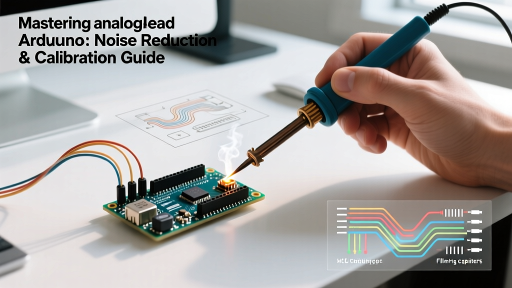
When beginners start with microcontrollers, reading a sensor is usually as simple as calling analogRead(A0). However, in professional environments or precision DIY projects, relying on the default implementation of the Arduino analogRead() reference often leads to jittery data, ghost readings, and inaccurate calibrations. Whether you are using a classic Arduino Uno R3 (ATmega328P) or the newer 14-bit ADC equipped Arduino Uno R4 Minima, understanding the physics and software optimizations behind the Analog-to-Digital Converter (ADC) is critical.
This comprehensive code walkthrough will take you beyond the basics. We will explore hardware impedance limits, multiplexer crosstalk, software noise filtering, and a clever oversampling technique to squeeze 12-bit resolution out of a 10-bit ADC.
The Physics of the ADC: Impedance and the Sample-and-Hold Capacitor
Before writing advanced code, you must understand the hardware. According to the ATmega328P Datasheet, the ADC multiplexer routes the analog signal to a Sample-and-Hold (S/H) capacitor, which is approximately 14pF. For the ADC to get an accurate reading, this capacitor must fully charge or discharge to match the input voltage during the acquisition time (roughly 1.5 ADC clock cycles).
The 10kΩ Impedance Rule
If your sensor has a high output impedance (e.g., a voltage divider using 100kΩ resistors or a passive LDR circuit), the 14pF capacitor cannot charge fast enough. The result is an artificially low or fluctuating reading. Microchip officially recommends an input impedance of 10kΩ or less. If your sensor exceeds this, you must either:
- Add a buffer op-amp: Use a low-noise rail-to-rail op-amp like the MCP6001 (approx. $0.35/ea) to drive the ADC pin.
- Add a decoupling capacitor: Place a 100nF ceramic capacitor directly between the analog input pin and GND. This acts as a local charge reservoir, effectively lowering the AC impedance seen by the ADC.
Edge Case: Multiplexer Crosstalk and Ghost Readings
One of the most frustrating bugs in multi-sensor Arduino projects is multiplexer crosstalk. Suppose you are reading a low-impedance sensor on A0 (like a 1kΩ potentiometer) and a high-impedance sensor on A1 (like a 100kΩ thermistor divider).
Expert Insight: If you read A0 and immediately read A1 in your loop(), the value returned for A1 will often be 'pulled' toward the voltage of A0. The S/H capacitor retained the charge from A0, and the high-impedance A1 circuit couldn't overpower it in time.
The Software Fix for Crosstalk
You do not necessarily need to redesign your hardware. You can fix this in software by reading the high-impedance pin twice and discarding the first reading. This gives the S/H capacitor time to settle.
// Crosstalk Mitigation Strategy
int readHighImpedancePin(int pin) {
  analogRead(pin); // Prime the S/H capacitor (discard this value)
  delayMicroseconds(10); // Optional: allow extra settling time
  return analogRead(pin); // Return the accurate, settled reading
}
Advanced Code Walkthrough: Software Noise Filtering
Even with perfect wiring, electromagnetic interference (EMI) from nearby motors, switching power supplies, or even the microcontroller's own digital clock can introduce high-frequency noise into your ADC readings. The Arduino ADC guide highlights that environmental noise is inevitable. Instead of relying solely on hardware low-pass filters, we can implement an Exponential Moving Average (EMA) filter in code.
Why EMA over a Simple Moving Average (SMA)?
A Simple Moving Average requires storing an array of past values, consuming precious SRAM (especially on ATmega328P boards with only 2KB). An EMA requires only a single floating-point variable to store the historical state, making it highly memory-efficient and computationally lightweight.
// Exponential Moving Average (EMA) Filter
const float EMA_ALPHA = 0.05; // Lower = smoother but more lag (0.01 to 0.1 is typical)
float ema_filtered_value = 0.0;
bool is_initialized = false;

float getFilteredAnalog(int pin) {
  int raw_sample = analogRead(pin);

  if (!is_initialized) {
    ema_filtered_value = raw_sample;
    is_initialized = true;
  } else {
    // EMA Formula: New = (Alpha * Current) + ((1 - Alpha) * Previous)
    ema_filtered_value = (EMA_ALPHA * raw_sample) + ((1.0 - EMA_ALPHA) * ema_filtered_value);
  }

  return ema_filtered_value;
}
Tuning the Alpha: An alpha of 0.1 provides a responsive but slightly noisy output. An alpha of 0.01 provides ultra-smooth data but introduces phase lag, which is detrimental for fast-reacting control loops like PID motor controllers.
Hardware Hack: Oversampling for 12-Bit Resolution
The ATmega328P features a 10-bit ADC, yielding values from 0 to 1023. If you are measuring a 5V reference, your resolution is roughly 4.88mV per step. For precision applications like RTD temperature sensing or load cells, this is insufficient. By utilizing a mathematical technique called oversampling and decimation, we can artificially achieve 12-bit resolution (0 to 4095), dropping the step size to 1.22mV.
The Math Behind Oversampling
To gain n extra bits of resolution, you must oversample by 4^n times. To gain 2 extra bits (10-bit to 12-bit), we need 4^2 = 16 samples. We sum these 16 samples and then divide by 4 (which is computationally identical to a bitwise right-shift by 2).
// 12-bit ADC Resolution via 16x Oversampling
unsigned int read12bitADC(int pin) {
  unsigned long sum = 0;

  // Take 16 rapid samples
  for (int i = 0; i < 16; i++) {
    sum += analogRead(pin);
  }

  // Decimate: Divide by 4 using bitwise right shift for speed
  return sum >> 2;
}
Note: This technique requires a small amount of inherent analog noise (dithering) to work correctly. If your signal is completely noise-free, the ADC will return the exact same 10-bit value 16 times, and oversampling will not yield extra resolution. In real-world scenarios, thermal noise usually provides enough dithering naturally.
Calibration Matrix: Mapping Raw ADC to Real-World Units
Raw ADC values (0-1023) are useless without calibration. The mapping formula is: Voltage = (Raw_ADC * Vref) / 1023.0. However, assuming Vref is exactly 5.0V via the USB line is a critical mistake. USB voltage can sag to 4.75V under load, skewing all sensor data. For precision, use the INTERNAL 1.1V reference or an external precision voltage reference IC like the LM4040 ($1.50 on Mouser).
Below is a calibration matrix for common sensors assuming a stable 5.00V VREF and 10-bit resolution:
| Sensor Type | Model / Spec | Raw ADC Range | Voltage Range | Real-World Mapping Formula |
|---|---|---|---|---|
| Temperature | TMP36 (Analog) | 102 - 307 | 0.5V - 1.5V | TempC = ((raw * 5.0 / 1024.0) - 0.5) * 100.0 |
| Light | GL5528 LDR + 10k Pull-down | 0 - 1023 | 0.0V - 5.0V | Requires Steinhart-Hart or logarithmic curve fit |
| Current | ACS712 (20A Module) | 409 - 614 | 2.0V - 3.0V | Amps = (raw - 512) * (5.0 / 1024.0) / 0.100 |
| Position | 10k Linear Potentiometer | 0 - 1023 | 0.0V - 5.0V | Angle = map(raw, 0, 1023, 0, 270) |
Summary of Best Practices for Production Code
- Never trust USB VREF: If your project relies on accurate absolute voltage measurements, call
analogReference(INTERNAL)to use the microcontroller's internal 1.1V bandgap reference, or provide a clean external reference to the AREF pin. - Mitigate Crosstalk: Always discard the first reading when switching the multiplexer between pins with vastly different source impedances.
- Filter Intelligently: Use EMA filtering for memory-constrained environments, reserving SMA or FIR filters for high-end ARM Cortex boards where DSP libraries are available.
- Oversample for Precision: Implement the 16x oversampling bitwise-shift trick when you need 12-bit resolution without upgrading to a dedicated external ADC like the ADS1115 ($4.00 breakout).
By treating the ADC not just as a simple function call, but as a complex electromechanical system requiring impedance matching, timing management, and digital signal processing, you elevate your Arduino projects from hobbyist prototypes to robust, production-ready instrumentation.