
Mastering the HC 05 Bluetooth Module with Arduino in 2026
As of 2026, while ESP32 native BLE and WiFi dominate new IoT designs, the HC 05 Bluetooth module with Arduino remains an undisputed staple for retrofitting legacy RS-232 industrial equipment, building heavy-duty RC robotics, and creating continuous serial bridges. Unlike Bluetooth Low Energy (BLE), which requires complex GATT characteristic negotiations, the HC-05 utilizes Bluetooth 2.0 Classic Serial Port Profile (SPP). This allows for unthrottled, high-throughput UART passthrough that behaves exactly like a physical serial cable.
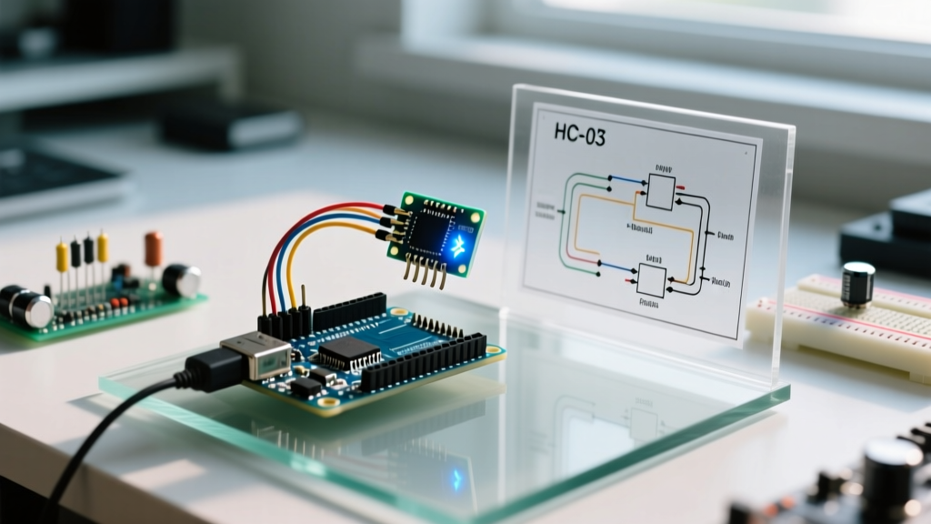
In this comprehensive code tutorial and walkthrough, we will bypass the superficial wiring diagrams found elsewhere and dive deep into the electrical realities, AT command state machines, and optimized C++ code required to build a robust Bluetooth-controlled system.
The Hardware Reality: Pricing, Clones, and the 5V Trap
Before writing a single line of code, we must address the electrical edge cases that destroy 80% of HC-05 modules in beginner projects. The HC-05 operates at 3.3V logic. However, standard 5V Arduinos (like the Uno or Mega) output 5V on their TX pins.
Expert Warning: Feeding 5V directly into the HC-05 RX pin will not immediately kill the module, but it will degrade the internal baseband controller's silicon over a few weeks, leading to intermittent pairing failures and the dreaded 'flashing red LED of death'. Always use a voltage divider.
Wiring Matrix and Voltage Divider Math
To safely interface the 5V Arduino with the 3.3V HC-05, we use a simple resistor voltage divider on the RX line. Using a 1kΩ and 2kΩ resistor yields:
Vout = 5V × (2000 / (1000 + 2000)) = 3.33V — perfectly within the HC-05's tolerance.
| HC-05 Pin | Arduino Uno Pin | Connection Notes & Requirements |
|---|---|---|
| VCC | 5V | Do NOT use the 3.3V pin; the module requires ~30mA during pairing and up to 200mA during transmission. The 3.3V regulator on the Uno cannot supply this. |
| GND | GND | Common ground is mandatory for serial reference. |
| TXD | Pin 10 (Software RX) | Direct connection. HC-05 TX outputs 3.3V, which the Uno reliably reads as a logical HIGH. |
| RXD | Pin 11 (Software TX) | Voltage Divider Required. 1kΩ resistor from Pin 11 to RXD; 2kΩ resistor from RXD to GND. |
| EN / KEY | Pin 9 | Pull HIGH (3.3V or 5V) during boot to enter AT Command Mode. |
Market Note: Genuine Z-TEK HC-05 modules hover around $11.50, while mass-produced clones (often based on BK8000L chips) sell for $3.80 to $5.20. Clones frequently lack proper LDO regulation, making the 5V VCC connection risky if your Arduino's 5V rail has ripple. Adding a 100µF decoupling capacitor across the HC-05 VCC and GND pins is highly recommended for clone modules.
Phase 1: Entering AT Command Mode
The HC-05 has two distinct operational modes: Data Mode (default, 9600 baud) and AT Command Mode (configuration, 38400 baud). To change the device name, PIN, or set it as a Master for point-to-point networking, you must enter AT mode.
According to the definitive HC-05 AT Mode guide by Martyn Currey, the most reliable way to enter AT mode is by pulling the EN/KEY pin HIGH before applying power to the module.
AT Configuration Code Walkthrough
Upload this sketch to your Arduino. It initializes the SoftwareSerial library—documented extensively in the official Arduino SoftwareSerial documentation—and bridges the hardware serial monitor to the HC-05 at the required 38400 baud.
#include <SoftwareSerial.h>

// Pin 10 is RX, Pin 11 is TX
SoftwareSerial BTSerial(10, 11);
const int enPin = 9;

void setup() {
  pinMode(enPin, OUTPUT);
  digitalWrite(enPin, HIGH); // Pull EN HIGH before booting HC-05

  Serial.begin(9600);
  Serial.println("Enter AT commands (Ensure NL & CR in Serial Monitor):");

  // HC-05 AT mode baud rate is strictly 38400
  BTSerial.begin(38400);
}

void loop() {
  // Bridge Hardware Serial to Software Serial
  if (BTSerial.available()) {
    Serial.write(BTSerial.read());
  }
  if (Serial.available()) {
    BTSerial.write(Serial.read());
  }
}
Essential AT Commands for Robotics
Once the code is running, open the Arduino IDE Serial Monitor, set the baud rate to 9600, and select Both NL & CR. Type the following commands to configure your module:
| AT Command | Expected Response | Function & Use Case |
|---|---|---|
AT |
OK |
Verifies communication. If no response, check wiring and baud rates. |
AT+NAME=FluxBot |
OK |
Changes the broadcast name. Crucial when multiple robots are in the same arena. |
AT+PSWD=8675 |
OK |
Changes the pairing PIN. Default is usually 1234 or 0000. |
AT+UART=115200,0,0 |
OK |
Increases Data Mode baud rate to 115200 for high-speed sensor telemetry. |
AT+ROLE=1 |
OK |
Sets module as Master. Required if the HC-05 needs to auto-connect to another HC-05 without a phone. |
Phase 2: Data Mode and State-Machine Programming
Once configured, disconnect the EN pin from 5V (tie it to GND or leave it floating) and reset the module. It will now boot into Data Mode. The LED will blink twice per second, indicating it is ready to pair.
For this walkthrough, we will build a non-blocking serial parser. Many beginners use delay() or blocking while(Serial.available()) loops, which starves the main loop and causes motor control jitter in robotics. We will use a character-by-character state machine.
Non-Blocking Serial Parser Code
This code reads incoming Bluetooth commands formatted as <CMD:VALUE> (e.g., <SPD:255> for speed, <DIR:FWD> for direction) without halting the microcontroller.
#include <SoftwareSerial.h>

SoftwareSerial BTSerial(10, 11); // RX, TX

String inputString = "";
bool stringComplete = false;

void setup() {
  Serial.begin(9600);
  // Match this to the UART setting you configured in AT mode
  BTSerial.begin(9600);
  inputString.reserve(32); // Prevent heap fragmentation
}

void loop() {
  readBluetooth();

  if (stringComplete) {
    processCommand(inputString);
    inputString = "";
    stringComplete = false;
  }

  // Your motor control or sensor polling code goes here
  // It will run continuously without being blocked by serial reads
}

void readBluetooth() {
  while (BTSerial.available()) {
    char inChar = (char)BTSerial.read();
    if (inChar == '<') {
      inputString = ""; // Reset buffer on start character
    } else if (inChar == '>') {
      stringComplete = true;
    } else {
      inputString += inChar;
    }
  }
}

void processCommand(String cmd) {
  int colonIndex = cmd.indexOf(':');
  if (colonIndex == -1) return; // Malformed packet

  String key = cmd.substring(0, colonIndex);
  String value = cmd.substring(colonIndex + 1);

  if (key == "SPD") {
    int speed = value.toInt();
    Serial.print("Setting Speed to: ");
    Serial.println(speed);
    // analogWrite(motorPin, constrain(speed, 0, 255));
  }
  else if (key == "DIR") {
    Serial.print("Setting Direction to: ");
    Serial.println(value);
    // Set H-Bridge logic pins based on value
  }
}
Advanced Edge Cases and Troubleshooting
Even with perfect wiring, RF environments and power delivery issues can cause silent failures. Here is a diagnostic matrix for common HC-05 anomalies encountered in the field.
- Module pairs but drops connection under load: This is almost always a power brownout. When an H-bridge motor driver engages, it pulls sudden current, dropping the 5V rail below the HC-05's LDO dropout voltage. Fix: Add a 470µF electrolytic capacitor directly on the HC-05 VCC/GND pins.
- Garbage characters in Serial Monitor: You have a baud rate mismatch. If you changed the UART via AT commands to 115200, but your
BTSerial.begin()is still set to 9600, the data will be unreadable. Always verify yourAT+UARTsettings. - Cannot find module on iOS devices: Apple's iOS restricts Bluetooth Classic SPP profiles. The HC-05 will only show up on Android, Windows, and Linux. If you require iOS connectivity, you must abandon the HC-05 and migrate to a BLE module like the HM-10 or an ESP32, as detailed in the Bluetooth SIG's comparison of Classic vs. BLE architectures.
- AT commands return ERROR (16): This indicates a syntax error or unsupported command for your specific firmware version. Clone modules often ship with stripped-down firmware that lacks master/slave switching capabilities. Verify your firmware version using
AT+VERSION.
Summary and Next Steps
Integrating the HC 05 Bluetooth module with Arduino requires respecting the 3.3V logic limits, understanding the dual-baud-rate architecture of AT vs. Data modes, and implementing non-blocking serial parsers. By utilizing the voltage divider and state-machine code provided in this walkthrough, your wireless Arduino projects will achieve industrial-level reliability, free from the memory leaks and timing jitters that plague basic tutorials.
For your next iteration, consider exploring software-based checksums (like CRC8) appended to your <CMD:VALUE> strings to ensure data integrity in high-interference RF environments.