
The Shift to 2D CMOS: Arduino Barcode Reader Interfaces in 2026
Integrating an Arduino barcode reader into a project used to mean dealing with bulky 1D laser modules and fragile moving parts. As of 2026, the market has almost entirely shifted to solid-state 2D CMOS imagers. Modules like the Grow GM65-S or the EM1350 can now read 1D barcodes, QR codes, and DataMatrix symbols from OLED screens and paper for under $20. However, the hardware is only half the battle; the real engineering challenge lies in the communication protocol.
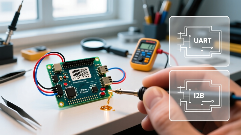
When you connect a scanner to a microcontroller, it doesn't just 'send text.' It relies on specific electrical signaling and data framing. This guide breaks down the three dominant protocols used to interface an Arduino barcode reader: UART (Serial), I2C, and USB HID, detailing the exact wiring, code structures, and edge cases that datasheets often omit.
Protocol Comparison Matrix
Before wiring your breadboard, you must select the right protocol for your system architecture. The choice depends on pin availability, processing overhead, and whether you are using an OEM embedded module or an off-the-shelf retail wand.
| Protocol | Typical Hardware | Pins Required | Data Speed | Best Use Case |
|---|---|---|---|---|
| UART | GM65-S, EM1350 | 2 (TX/RX) | 9600 - 115200 Baud | Continuous scanning, low-latency OEM integration |
| I2C | GM73, custom PCB modules | 2 (SDA/SCL) | 100 - 400 kHz | Multi-device buses, pin-constrained ATtiny/ESP setups |
| USB HID | Retail USB Wands, MAX3421E | 4 (USB D+/D-, VCC, GND) | 12 Mbps (Full Speed) | Rapid prototyping with off-the-shelf retail scanners |
1. UART (Serial): The Asynchronous Workhorse
UART (Universal Asynchronous Receiver-Transmitter) is the most common protocol for embedded Arduino barcode reader projects. The scanner acts as a TX-only device, pushing ASCII or hexadecimal bytes the moment a barcode is successfully decoded.
Wiring and Logic Levels
Connect the scanner's TX pin to the Arduino's RX pin. If you are using a 5V Arduino Uno, ensure your scanner supports 5V logic. Many modern OEM modules (like the GM65-S) operate natively at 3.3V. Feeding 5V into a 3.3V RX line will degrade the module's internal ESD protection diodes over time. Use a simple BSS138 MOSFET-based logic level shifter or a voltage divider (e.g., 2kΩ and 3.3kΩ resistors) to step down the Arduino's 5V TX line if your scanner requires bidirectional configuration commands.
Code Implementation & Buffer Management
We use the SoftwareSerial library to free up the hardware Serial port (pins 0 and 1) for debugging via the Serial Monitor.
#include <SoftwareSerial.h>

// RX on pin 10, TX on pin 11
SoftwareSerial barcodeScanner(10, 11);

String scanData = "";
unsigned long lastReadTime = 0;

void setup() {
  Serial.begin(115200);
  // Most OEM modules default to 9600 baud
  barcodeScanner.begin(9600);
}

void loop() {
  while (barcodeScanner.available()) {
    char c = barcodeScanner.read();
    // Check for Carriage Return (CR) or Line Feed (LF)
    if (c == '\r' || c == '\n') {
      if (scanData.length() > 0) {
        Serial.println("Scanned: " + scanData);
        scanData = ""; // Clear buffer
        lastReadTime = millis();
      }
    } else {
      scanData += c;
    }
  }
}
Expert Edge Case: Datasheet suffix mismatches are the #1 cause of concatenated scans. If your scanner is configured in the factory to output a Tab (\t) instead of a Carriage Return (\r) after a scan, theif (c == '\r')condition will fail. The buffer will continuously grow until it crashes the SRAM. Always scan the 'Factory Reset' and 'Add CR Suffix' configuration barcodes found in the module's manual before writing your parsing logic.
2. I2C: The Addressable Approach
I2C is ideal when your Arduino is already pin-starved or when you are integrating the barcode reader into a larger sensor bus. Unlike UART, where the scanner blindly pushes data, I2C requires the Arduino (the Master) to poll the scanner (the Slave) to retrieve the decoded data.
The Clock Stretching Problem
When a scanner decodes a complex 2D QR code, its internal processor may take 50-100ms to process the image. During this time, if the Arduino requests data via I2C, the scanner will hold the SCL (clock) line LOW—a mechanism known as clock stretching. Cheap Arduino clones using the CH340 USB-to-Serial chip or older ATmega328P bootloaders sometimes fail to handle clock stretching correctly, resulting in I2C bus lockups. If you experience random freezes, implement a software watchdog or use an Arduino with a hardware I2C peripheral that fully supports stretching (like the SAMD21 or ESP32).
Polling Implementation
#include <Wire.h>

// Common I2C address for Grow embedded scanners
#define SCANNER_I2C_ADDR 0x42

void setup() {
  Serial.begin(115200);
  Wire.begin();
  // Set I2C clock to 100kHz for stability
  Wire.setClock(100000);
}

void loop() {
  Wire.requestFrom(SCANNER_I2C_ADDR, 32); // Request up to 32 bytes

  String payload = "";
  while (Wire.available()) {
    char c = Wire.read();
    if (c != 0x00) { // Ignore null padding bytes
      payload += c;
    }
  }

  if (payload.length() > 0) {
    Serial.println("I2C Scan: " + payload);
  }
  delay(100); // Poll every 100ms
}
3. USB HID: Emulating a Keyboard
If you are using a retail USB barcode wand (the kind with a trigger and a USB-A plug), it operates as a USB Human Interface Device (HID). It literally emulates a standard keyboard, typing out the barcode characters at lightning speed. Because the Arduino Uno lacks native USB Host capabilities, you must use a MAX3421E-based USB Host Shield (costing around $12-$15 in 2026).
Boot Protocol vs. Report Protocol
Using the USB Host Shield 2.0 library, you can intercept the HID reports. The library's hidboot example is the standard starting point. However, a critical failure mode occurs when scanners use 'Report Protocol' instead of 'Boot Protocol'. Boot protocol guarantees a standard 8-byte keyboard packet. Report protocol allows the manufacturer to define custom packet structures for multi-byte UTF-8 characters or special function keys. If your scanner uses Report Protocol, the standard HIDBoot<USB_HID_PROTOCOL_KEYBOARD> class will return garbage data. You will need to subclass HIDReportParser and manually map the HID usage tables.
The Enumeration Delay
USB is not instant. When the Arduino powers on, the MAX3421E chip must negotiate power, assign an address, and read the HID descriptors. This USB enumeration process takes 1.5 to 3 seconds. If your system is designed to scan a barcode immediately upon power-up (e.g., a kiosk boot sequence), the scanner will miss the scan because the USB bus isn't ready. You must implement a state machine that waits for Usb.Init() == 0 and triggers a 'Ready' LED or buzzer only after the HID interface is successfully polled.
Real-World Troubleshooting & Failure Modes
Even with perfect code, physical layer issues frequently derail barcode integrations. Keep this diagnostic checklist on your bench:
- The 'Double Scan' Ghost: If your Arduino registers the same barcode twice, your scanner's 'Same Symbol Read Delay' is set too low. Use the module's configuration barcodes to increase the lockout time to 300ms, or implement a software debounce in your C++ code comparing the current string to the previous string with a
millis()timer. - QR Code Truncation: 2D codes can hold up to 4,296 alphanumeric characters. If you are using
SoftwareSerialwith a standard 64-byte buffer, scanning a dense QR code will cause a buffer overflow, dropping the last half of the data. Fix: Increase the_SS_MAX_RX_BUFFmacro in the SoftwareSerial.h file to 256, or switch to an Arduino Mega with multiple hardware UART ports. - I2C Address Conflicts: Many embedded scanners default to
0x08or0x42. If you are also using an OLED display (often0x3C) or an RTC module, ensure no addresses overlap. Most scanners allow you to change their I2C address by scanning a specific hex-code barcode from the manual.
Summary
Choosing the right protocol for your Arduino barcode reader dictates your system's reliability. Use UART for straightforward, low-latency OEM integrations; leverage I2C when pin conservation is paramount and you can manage polling overhead; and deploy USB HID via a Host Shield when you need to interface with retail, off-the-shelf wands. By understanding the underlying electrical framing and edge cases of each protocol, you can build robust scanning systems that survive the chaos of real-world deployment.