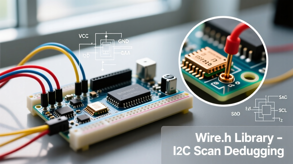

The Critical Role of I2C Scanning in Embedded Prototyping
When integrating new sensors into an embedded project, the first hurdle is almost always communication verification. Whether you are wiring up a genuine Bosch BME280 environmental sensor ($12.50) or a generic unmarked MPU6050 clone from an overseas marketplace ($2.15), confirming the device is electrically and logically present on the bus is mandatory. The Arduino scan I2C routine is the foundational diagnostic tool for this exact purpose. However, treating the I2C scanner as a simple copy-paste script often leads to misunderstood hardware faults, bus lockups, and ghost addresses. In this library deep dive, we deconstruct the underlying mechanics of the Arduino Wire library, analyze the physical layer constraints defined by the NXP I2C-bus specification (UM10204), and provide production-grade code to prevent catastrophic bus failures.
The Anatomy of an I2C Scan: What Happens Under the Hood?
To understand why an Arduino I2C scan fails, you must understand what the microcontroller is physically doing on the SDA (Serial Data) and SCL (Serial Clock) lines. The standard I2C protocol utilizes a 7-bit addressing scheme, allowing for 128 potential addresses (though 16 are reserved, leaving 112 usable nodes).
When you execute an I2C scan, the Arduino master performs the following sequence for every address from 0x08 to 0x77:
- Start Condition: The master pulls SDA low while SCL remains high.
- Address Byte Transmission: The master shifts out 7 bits of the target address, followed by an 8th bit indicating Read (1) or Write (0). Scanners typically use the Write bit (0).
- The 9th Clock Cycle (ACK/NACK): The master releases the SDA line and pulses SCL high. If a slave device recognizes its address, it pulls SDA low, generating an Acknowledge (ACK) bit. If no device responds, SDA remains high (pulled up by resistors), resulting in a Not Acknowledge (NACK).
- Stop Condition: The master releases SDA to high while SCL is high, terminating the transaction.
Expert Insight: The Arduino Wire library abstracts this via
Wire.beginTransmission(address)followed byWire.endTransmission(). The return value ofendTransmission()is the key to debugging. A return of0means an ACK was received. A return of2means a NACK was received on the address byte (device not found).
The Standard vs. Robust Scanner Implementation
The ubiquitous I2C scanner sketch found on countless forums works perfectly in ideal conditions. However, in real-world environments with long wires, high capacitance, or malfunctioning slave nodes, the standard scanner will hang indefinitely. This happens if a slave device crashes and holds the SDA line low, preventing the master from generating a Stop condition.
Modern AVR and ARM Arduino cores include a vital, often overlooked feature: I2C Timeouts. Below is a robust, production-ready scanner implementation that utilizes hardware timeouts to prevent bus lockups.
#include <Wire.h>

void setup() {
  Serial.begin(115200);
  while (!Serial); // Wait for serial monitor

  Wire.begin();
  // Set a 25,000 microsecond (25ms) timeout and enable bus reset on timeout
  Wire.setWireTimeout(25000, true);
  Serial.println("Robust I2C Scanner Initialized...");
}

void loop() {
  byte error, address;
  int nDevices = 0;

  Serial.println("Scanning I2C bus...");
  for(address = 1; address < 127; address++ ) {
    Wire.beginTransmission(address);
    error = Wire.endTransmission();

    if (error == 0) {
      Serial.print("I2C device found at address 0x");
      if (address < 16) Serial.print("0");
      Serial.print(address, HEX);
      Serial.println("  !");
      nDevices++;
    }
    else if (error == 5) {
      Serial.print("TIMEOUT at address 0x");
      if (address < 16) Serial.print("0");
      Serial.println(address, HEX);
      // The Wire library automatically resets the bus because of setWireTimeout(..., true)
    }
    else if (error == 4) {
      Serial.print("Unknown error at address 0x");
      if (address < 16) Serial.print("0");
      Serial.println(address, HEX);
    }
  }
  if (nDevices == 0) Serial.println("No I2C devices found. Check pull-ups and wiring.");
  else Serial.println("Scan complete.");

  delay(5000); // Wait 5 seconds before next scan
}
By invoking Wire.setWireTimeout(25000, true), we instruct the microcontroller's Two-Wire Interface (TWI) hardware to abort the transaction if the bus remains busy for 25 milliseconds, and the true parameter forces a hardware reset of the TWI peripheral, clearing the lockup without requiring a manual MCU reboot.
Hardware Bottlenecks: Pull-Ups, Capacitance, and Level Shifting
Software can only diagnose what the hardware allows. The most common reason an Arduino scan I2C routine fails to find a perfectly good sensor is improper bus physics. I2C is an open-drain protocol; devices can only pull the line low. They rely on external pull-up resistors to bring the line high.
Calculating Pull-Up Resistor Values
According to the Texas Instruments Application Report SLVA689, selecting the wrong pull-up resistor value will distort the signal edges, causing the Arduino to misread bits. The I2C specification mandates a maximum bus capacitance of 400 pF for standard mode (100 kHz) and fast mode (400 kHz).
| Bus Speed | Recommended Pull-Up (3.3V) | Recommended Pull-Up (5V) | Max Rise Time Limit |
|---|---|---|---|
| Standard (100 kHz) | 4.7 kΩ | 4.7 kΩ - 10 kΩ | 1000 ns |
| Fast (400 kHz) | 2.2 kΩ - 3.3 kΩ | 2.2 kΩ - 4.7 kΩ | 300 ns |
| Fast+ (1 MHz) | 1.0 kΩ - 2.2 kΩ | 1.0 kΩ - 2.2 kΩ | 120 ns |
Note: Most generic breakout boards (like the ubiquitous GY-BME280 or GY-NEO6M modules) include 10 kΩ surface-mount pull-up resistors tied to VCC. If you connect three of these modules to the same I2C bus, the resistors act in parallel, dropping the total resistance to ~3.3 kΩ, which is generally acceptable but alters the rise time.
Logic Level Shifting Edge Cases
Mixing 5V Arduinos (like the Uno R3 or Mega2560) with 3.3V sensors (like the SHT31 or LSM6DS3) requires a bidirectional logic level shifter. Do not use simple resistor dividers; they are unidirectional and will break the open-drain ACK/NACK mechanism. Instead, use a MOSFET-based shifter utilizing the BSS138 N-channel MOSFET, or a dedicated IC like the PCA9306. Ensure the pull-up resistors on the low-voltage side are sized correctly to account for the MOSFET's gate capacitance.
Diagnostic Matrix: Decoding Scan Failures
When your serial monitor outputs unexpected results, use this diagnostic matrix to pinpoint the exact failure mode.
| Scanner Output Symptom | Root Cause Analysis | Hardware / Software Fix |
|---|---|---|
| No devices found (Blank scan) | Missing pull-up resistors, swapped SDA/SCL wires, or dead 3.3V LDO on the sensor breakout. | Verify continuity with a multimeter. Add external 4.7kΩ pull-ups to VCC. Check voltage at the sensor's VCC pin. |
| Ghost Addresses (0x00, 0x7F, or random shifting) | Floating SDA/SCL lines picking up EMI, or missing pull-ups causing the master to read its own echo during the ACK phase. | Install proper pull-up resistors. Keep I2C traces under 30cm. Add a 100nF decoupling capacitor across the sensor's VCC/GND. |
| Scanner hangs indefinitely | A slave device has crashed and is holding SDA low, or SCL is shorted to ground. | Implement Wire.setWireTimeout(). Physically toggle the SCL line 9 times via GPIO to force the slave to release SDA. |
| Device found, but subsequent reads fail | Address conflict (e.g., two MPU6050s both defaulting to 0x68), or I2C clock speed exceeds sensor capability. | Change the ADO pin state on one sensor to shift its address to 0x69. Force bus speed: Wire.setClock(100000); |
Advanced Edge Case: The Infamous 0x7F Ghost Address
A highly specific and confusing edge case occurs when the Arduino scan I2C routine reports a device at 0x7F (or sometimes 0x00), even when the bus is completely empty. This is almost always a hardware artifact related to the microcontroller's internal TWI state machine or floating lines. When the SDA line lacks a strong pull-up, the internal sampling logic of the ATmega328P or ESP32 can misinterpret thermal noise or capacitive coupling from adjacent traces as a valid ACK bit on the 9th clock cycle. If you see 0x7F on an empty bus, your pull-up resistors are either missing, broken, or tied to the wrong voltage rail.
Production-Grade Alternatives to the Standard Scanner
For engineers moving from prototyping to production firmware, relying on a blocking for loop to scan the bus is inefficient. The Official Arduino Wire Library Reference provides the baseline, but community-maintained libraries offer superior diagnostics. Consider integrating the I2CScanner library by Rob Tillaart. It provides non-blocking scanning capabilities, detailed bus health metrics (including rise-time estimation), and specialized functions to detect specific device families by querying their WHO_AM_I registers, rather than just relying on the ACK bit. This is crucial when dealing with clone chips that acknowledge the I2C address but return garbage data over SPI/I2C due to faulty internal silicon.
Final Verification Steps
Before finalizing your embedded code, always perform a physical layer verification. Use a digital storage oscilloscope (DSO) or a cheap $12 USB logic analyzer (like the Saleae Logic clone running Sigrok/PulseView) to capture the SDA and SCL lines during the scan. Verify that the logic low voltage ($V_{OL}$) is strictly below 0.4V for 5V systems, and that the rise times do not exceed the limits dictated by your chosen bus speed. Mastering the physical and logical layers of the I2C protocol transforms the Arduino scan I2C routine from a simple troubleshooting trick into a powerful diagnostic instrument.