
The 2026 Landscape: Choosing Your WiFi Module Arduino Integration
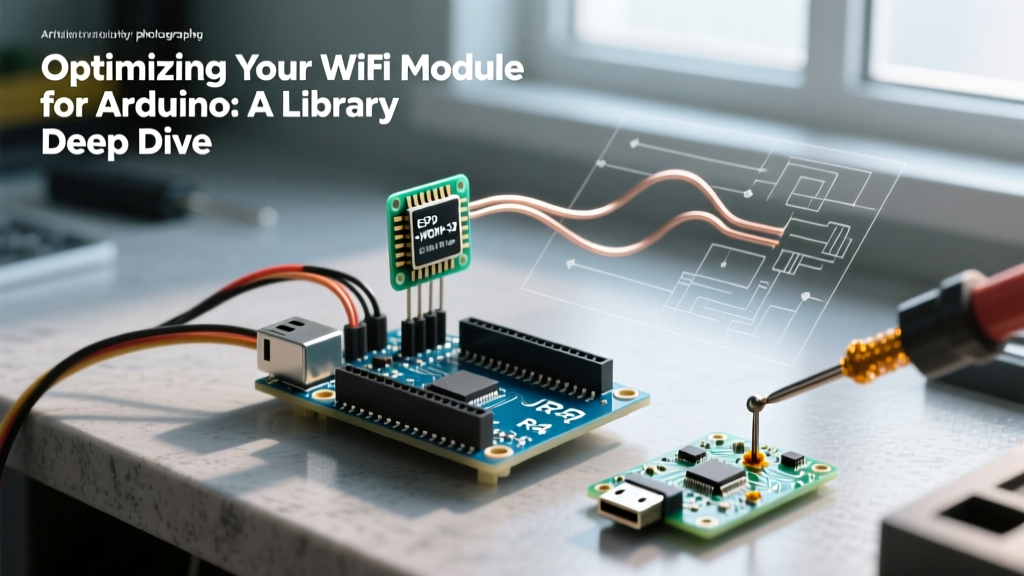
Integrating a WiFi module Arduino setup into your IoT projects has evolved significantly. While the classic ESP8266 (ESP-01S) remains a staple for legacy AT-command bridging, the modern ecosystem in 2026 is dominated by the ESP32-C3 and ESP32-S3 families. These native microcontrollers eliminate the need for a separate host MCU in most architectures, offering onboard WiFi 4, Bluetooth 5 (LE), and vastly superior power management. However, understanding how to interface traditional Arduino boards (like the Uno R4 or Nano Every) with dedicated WiFi modules, as well as programming standalone ESP modules via the Arduino IDE, remains a critical skill for electrical engineers and DIYers.
This guide provides a deep-dive communication setup, covering hardware wiring, logic-level translation, robust non-blocking code structures, and power-delivery edge cases that cause 90% of field failures.
Hardware Comparison Matrix: ESP8266 vs. ESP32-C3
Before writing a single line of code, selecting the right hardware dictates your wiring topology and memory management strategy. Below is a technical comparison of the most popular modules used in Arduino ecosystems today.
| Feature | ESP-01S (ESP8266) | ESP32-C3 SuperMini | ESP32-S3-WROOM-1 |
|---|---|---|---|
| Primary Role | AT-Command WiFi Bridge | Standalone IoT Node / Bridge | High-Performance AI/Vision Node |
| 2026 Avg. Price | $2.80 - $3.50 | $2.20 - $2.60 | $4.50 - $5.50 |
| Logic Level | 3.3V (5V Intolerant) | 3.3V (5V Intolerant) | 3.3V (5V Intolerant) |
| Peak TX Current | ~350mA | ~240mA | ~380mA |
| Flash / SRAM | 1MB / 50KB | 4MB / 400KB | 8MB+ / 512KB + PSRAM |
| Arduino IDE Core | ESP8266 Community (v3.1.x) | Espressif Arduino-ESP32 (v3.0.x) | Espressif Arduino-ESP32 (v3.0.x) |
Wiring the ESP-01S: Avoiding the 5V Logic Trap
If your project requires using a standard 5V Arduino (like the Uno R3) to communicate with an ESP-01S via UART, you must implement hardware logic level shifting. The ESP8266 GPIO pins are strictly 3.3V tolerant; feeding them 5V from an Arduino TX pin will degrade the silicon and eventually cause a hard short.
The Voltage Divider Solution
For unidirectional communication (Arduino TX to ESP RX), a simple resistor voltage divider is sufficient and costs pennies.
- R1 (Series Resistor): 1kΩ connected to Arduino TX (Pin 1).
- R2 (Pull-down Resistor): 2kΩ connected between ESP RX (U0RXD) and GND.
- Result: 5V * (2k / (1k + 2k)) = 3.33V at the ESP RX pin.
Note: The ESP TX to Arduino RX line does not require a divider, as the Arduino's ATmega328P reliably reads 3.3V as a logic HIGH (Vih threshold is typically 0.6 * VCC, or 3.0V, but 3.3V is safely recognized in almost all real-world conditions).
Critical Boot Pin Configurations
A common failure mode for beginners is the ESP-01S failing to boot into normal execution mode. According to the official Espressif hardware guidelines, you must manage the following pins:
- CH_PD (EN): Must be pulled HIGH to 3.3V via a 10kΩ resistor. If left floating, the module will randomly reset.
- GPIO0: Must be pulled HIGH to 3.3V via a 10kΩ resistor for normal boot. Pulling it LOW forces the module into UART bootloader (flash) mode.
- GPIO2: Must be pulled HIGH to 3.3V via a 10kΩ resistor during boot.
Native ESP32 Arduino IDE Setup & Robust Coding
When using an ESP32 module natively within the Arduino IDE, relying on the standard blocking WiFi.begin() loop is a recipe for watchdog timer (WDT) resets and poor user experience. Modern IoT firmware requires event-driven, non-blocking WiFi management.
Implementing WiFi Event Handlers
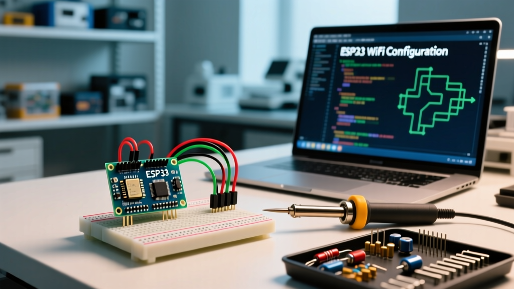
Instead of trapping the MCU in a while() loop waiting for a connection, we utilize the WiFi.onEvent() callback. This allows the main loop to continue polling sensors while the radio handles connection state changes in the background. As detailed in resources like Random Nerd Tutorials' ESP32 WiFi Functions guide, handling disconnect events gracefully is vital for remote deployments.
#include <WiFi.h>

const char* ssid = "YourNetworkSSID";
const char* password = "YourNetworkPassword";

// Event Handler Callbacks
void WiFiEvent(WiFiEvent_t event) {
    switch(event) {
        case ARDUINO_EVENT_WIFI_STA_GOT_IP:
            Serial.print("[WiFi] Connected. IP: ");
            Serial.println(WiFi.localIP());
            break;
        case ARDUINO_EVENT_WIFI_STA_DISCONNECTED:
            Serial.println("[WiFi] Disconnected. Attempting reconnect...");
            WiFi.setAutoReconnect(true);
            WiFi.reconnect();
            break;
        default:
            break;
    }
}

void setup() {
    Serial.begin(115200);

    // Delete old config to prevent NVS corruption bugs
    WiFi.disconnect(true);
    delay(1000);

    // Register Event Handler
    WiFi.onEvent(WiFiEvent);

    // Set Hostname for mDNS / Router DHCP tables
    WiFi.setHostname("FluxNode-01");

    // Initiate Connection
    WiFi.mode(WIFI_STA);
    WiFi.begin(ssid, password);
}

void loop() {
    // Non-blocking sensor reading and MQTT publishing goes here
    delay(10); // Yield to RTOS WiFi task
}
Power Supply Edge Cases & Brownout Troubleshooting
The most frequently reported issue in module Arduino WiFi setups is the dreaded Brownout detector was triggered serial error, followed by an infinite boot loop. This is rarely a code issue; it is a physics issue.
Expert Insight: When an ESP32 or ESP8266 transmits a WiFi packet, the RF power amplifier draws a sudden current spike (up to 350mA for the ESP8266). If your power supply or USB cable has high internal resistance, the voltage rail will momentarily sag below the brownout threshold (typically 2.43V), causing the hardware reset circuit to trigger.
The Decoupling Capacitor Fix
To stabilize the VCC rail during RF TX bursts, you must place decoupling capacitors as physically close to the module's VCC and GND pins as possible.
- Bulk Storage: Place a 100µF to 220µF Tantalum or low-ESR Electrolytic capacitor across 3.3V and GND. This handles the macro-level current spikes of WiFi transmission.
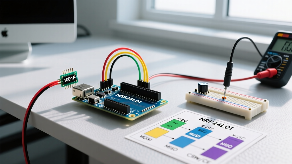
- High-Frequency Filtering: Place a 100nF (0.1µF) ceramic capacitor in parallel with the bulk capacitor. This filters out high-frequency switching noise from the internal DC-DC converters.
If you are powering the module from an Arduino's onboard 3.3V regulator, be aware that standard AMS1117-3.3 regulators on clone boards often max out at 800mA and lack adequate heatsinking. For continuous WiFi transmission, power the module from a dedicated 3.3V buck converter (like the AMS1117 or MP1584EN) tied to the Arduino's 5V or VIN rail.
Securing the Connection: MQTT and TLS Integration
Once your WiFi module is reliably connected to the local network, the next step in a professional communication setup is establishing a secure telemetry pipeline. In 2026, sending unencrypted HTTP GET requests to a PHP script is considered a severe security vulnerability. The industry standard is MQTT over TLS (MQTTS) on port 8883.
When utilizing the OASIS MQTT v5.0 specification with the ESP32, you must account for the memory overhead of TLS handshakes. A standard TLS 1.2 connection requires roughly 45KB to 60KB of SRAM for the mbedTLS library buffers.
Memory Optimization for TLS
- Use PSRAM: If using an ESP32-S3 or WROVER, configure the Arduino IDE to use "OAT (Optimized Allocation for TLS)" in the Tools menu to offload mbedTLS buffers to external PSRAM.
- Reduce Fragmentation: Avoid using the
Stringclass for MQTT payload construction. Use fixed-sizechararrays orArduinoJsonwith pre-allocatedJsonDocumentsizes to prevent heap fragmentation, which leads to allocation failures during the TLS handshake. - WPA3-SAE: The ESP32-C3 and S3 natively support WPA3-Personal (SAE). Ensure your router is configured for WPA2/WPA3 transition mode to leverage the enhanced cryptographic handshake without breaking backward compatibility with older ESP8266 nodes.
Summary Checklist for Field Deployment
Before deploying your WiFi module Arduino node into the field, verify the following:
- [ ] Logic levels are shifted if interfacing 5V MCUs with 3.3V WiFi modules.
- [ ] EN/CH_PD and GPIO0 pins have appropriate 10kΩ pull-up resistors.
- [ ] 100µF and 100nF decoupling capacitors are soldered directly at the module power pins.
- [ ] Firmware utilizes non-blocking
WiFi.onEvent()handlers instead ofwhile()loops. - [ ] Watchdog timers are configured to reset the MCU if the WiFi stack hangs for > 30 seconds.
By adhering to these hardware and software best practices, your IoT nodes will achieve the multi-year uptime and reliability required for professional electrical and electronic deployments.