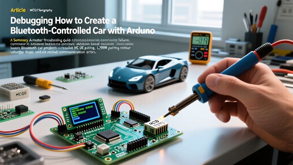

The Reality of Arduino Bluetooth Car Projects
If you are searching for a guide on how to create a bluetooth-controlled car with arduino, you have likely already assembled the chassis, wired the motors, and uploaded a sketch—only to find that the car spins in circles, refuses to pair, or resets the moment you apply throttle. As of 2026, while modern ESP32 and BLE modules dominate advanced IoT designs, the classic HC-05 Bluetooth module paired with an ATmega328P-based Arduino Uno or Nano remains the standard for educational kits and hobbyist入门 projects.
However, 90% of failures in these builds do not stem from broken components, but from compounding engineering oversights: voltage starvation, logic-level mismatches, and blocking serial code. This diagnostic guide bypasses the basic wiring tutorials and dives straight into the advanced troubleshooting required to get your rover moving reliably.
Phase 1: Diagnosing Power Starvation and Brownouts
The most common symptom of a failing Bluetooth car is the 'Arduino Reset Loop.' You send a command from your smartphone, the motors twitch, the HC-05 LED drops out, and the Arduino reboots. This is a classic brownout caused by inadequate current delivery.
The 9V Alkaline Mistake
Beginner kits often suggest using a standard 9V PP3 alkaline battery. This is a critical error. A 9V alkaline battery has an internal resistance that causes severe voltage sag under the 1A+ load of four DC geared motors. When the voltage drops below 3.3V, the HC-05 module crashes, and the Arduino's onboard voltage regulator starves.
Expert Recommendation: Ditch the 9V battery and AA holders. Use a 2S (7.4V nominal, 8.4V fully charged) 18650 Li-ion battery pack. High-drain cells like the Sony VTC6 or Samsung 25R can deliver 20A+ continuously, ensuring rock-solid voltage even during hard acceleration. For a deep dive into Li-ion discharge characteristics, consult the Battery University Lithium-Ion Guide.
The L298N Voltage Drop Penalty
The ubiquitous red L298N dual H-bridge motor driver is based on bipolar junction transistor (BJT) technology. According to the STMicroelectronics L298 Datasheet, this architecture introduces a voltage drop of approximately 2V to 3V across the internal transistors. If you supply 7.4V from a 2S Li-ion pack, your motors are only receiving ~4.5V. Furthermore, the L298N's onboard 5V linear regulator will overheat and shut down if the input voltage exceeds 12V or if you attempt to draw more than 500mA from the 5V tap to power your Arduino.
Phase 2: HC-05 Bluetooth Pairing and Baud Rate Mismatches
If your smartphone app connects but the car ignores your commands, you are likely facing a baud rate mismatch or a line-ending parsing error. While standard HC-05 modules ship at a default baud rate of 9600, many cheap clones from recent manufacturing batches are hardcoded to 38400 or 115200.
Entering AT Command Mode
To verify and force the baud rate, you must access the HC-05's AT command mode. Follow this exact sequence:
- Disconnect power from the HC-05.
- Press and hold the tiny tactile button on the HC-05 module.
- Apply power while continuing to hold the button for 3 seconds, then release. The LED should now blink slowly (once every 2 seconds).
- Open the Arduino IDE Serial Monitor. Set the baud rate to 38400 (the default AT mode speed) and set line endings to Both NL & CR.
Crucial AT Commands
Type the following commands to standardize your module:
AT(Should returnOK)AT+UART=9600,0,0(Forces communication baud rate to 9600 with 1 stop bit and no parity)AT+NAME=FluxRover(Changes the visible Bluetooth SSID)AT+PSWD=1234(Sets the pairing PIN)
Phase 3: Logic Level Shifting (The Silent Module Killer)
The Arduino Uno operates at 5V logic. The HC-05's TX pin outputs 3.3V, which the Arduino easily reads as a HIGH signal. However, the Arduino's TX pin outputs 5V into the HC-05's RX pin. The HC-05 is strictly a 3.3V device. Feeding 5V directly into the RX pin will degrade the module's internal traces over time and eventually destroy the Bluetooth SoC.
The Fix: You must build a voltage divider on the wire connecting the Arduino TX to the HC-05 RX. Use a 1kΩ resistor in series with the signal, and a 2kΩ resistor pulling the signal to ground. This drops the 5V signal down to a safe ~3.3V.
Phase 4: Motor Driver Wiring & Modern Alternatives
If your code is verified and power is stable, but motors refuse to spin or only spin in one direction, check your PWM and jumper configurations.
| Feature | L298N (Classic) | TB6612FNG (Modern) |
|---|---|---|
| Architecture | BJT (Bipolar) | MOSFET |
| Voltage Drop | ~2.0V - 3.0V | ~0.5V |
| Max Continuous Current | 2A per channel | 1.2A per channel (3A peak) |
| Logic Level | 5V tolerant | 3.3V / 5V tolerant |
| Standby Current | High (mA range) | Near Zero (µA range) |
Common L298N Wiring Fault: The ENA and ENB pins control the speed via PWM. If you leave the plastic jumper caps on ENA and ENB, the motors are locked to 100% speed (5V logic HIGH). To enable speed control via your smartphone app's joystick, you must remove the jumper caps and wire ENA and ENB to Arduino PWM-capable pins (marked with a ~ symbol, such as pins 5, 6, 9, or 10).
Phase 5: Bulletproof Serial Parsing in C++
Many tutorials on how to create a bluetooth-controlled car with arduino rely on Serial.readString() or Serial.readStringUntil(). This is a catastrophic coding practice for real-time motor control. These functions are blocking—they halt the Arduino's main loop while waiting for a timeout, causing severe stuttering and delayed braking.
The Non-Blocking Single-Character Approach
Instead of sending strings like 'FORWARD', configure your smartphone app (using MIT App Inventor or similar) to send single ASCII characters: 'F' (Forward), 'B' (Back), 'L' (Left), 'R' (Right), 'S' (Stop). Use the non-blocking Arduino SoftwareSerial or hardware Serial buffer check:
#include <SoftwareSerial.h>
SoftwareSerial BTSerial(2, 3); // RX, TX

char command;

void setup() {
  BTSerial.begin(9600);
  // Initialize motor pins as OUTPUT here
}

void loop() {
  // Non-blocking serial read
  if (BTSerial.available() > 0) {
    command = BTSerial.read();

    switch (command) {
      case 'F':
        moveForward(255);
        break;
      case 'B':
        moveBackward(255);
        break;
      case 'L':
        turnLeft(200);
        break;
      case 'R':
        turnRight(200);
        break;
      case 'S':
        stopMotors();
        break;
    }
  }
  // Other non-blocking sensor code can run here seamlessly
}

void moveForward(int speed) {
  // Set direction pins and analogWrite() to ENA/ENB
}

void stopMotors() {
  // Set all motor pins LOW
}
Final Pre-Flight Diagnostic Checklist
Before tearing your chassis apart, run through this rapid diagnostic sequence:
- Voltage Check: Measure the voltage at the L298N 5V terminal while the motors are stalled. If it drops below 4.5V, your power supply is failing.
- TX/RX Swap: If the HC-05 pairs but receives zero data, swap the RX and TX wires. It is the most common physical wiring error.
- Ground Loop: Ensure the Arduino GND, the Motor Driver GND, and the Battery GND are all tied together on a single common ground bus. Without a shared ground, logic signals will float and fail.
- App Verification: Use a generic 'Bluetooth Terminal' app on your phone to manually send 'F' and 'B' characters. If the car responds to the terminal but not your custom joystick app, the bug is in your app's string formatting, not the Arduino.
By isolating the power delivery, securing the logic levels, and implementing non-blocking serial parsing, your Arduino Bluetooth car will transition from a frustrating desk ornament to a highly responsive, reliable robotic platform.