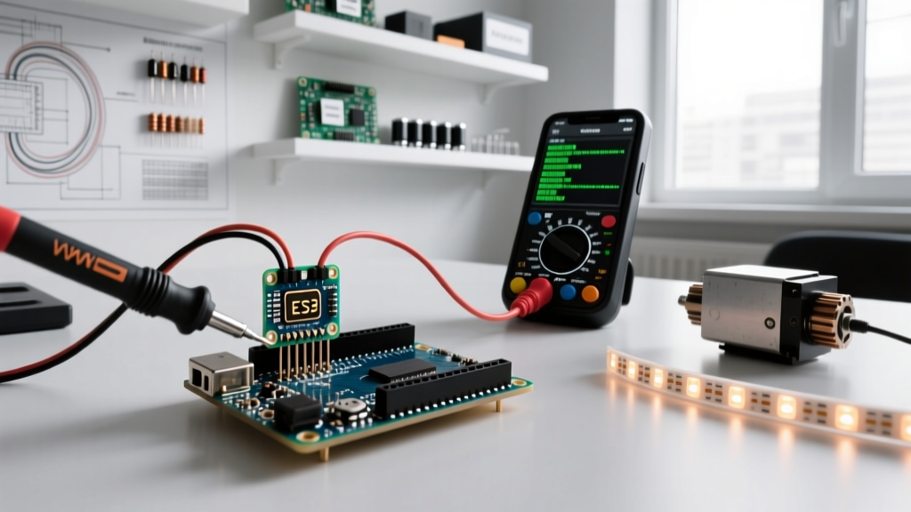

The Hidden Cost of analogWrite() Abstraction
Pulse Width Modulation (PWM) is the backbone of analog output simulation in embedded systems. However, when debugging pulse width modulation Arduino code, developers frequently hit a wall created by the very function designed to help them: analogWrite(). While this function abstracts away the complexities of hardware timers, it also masks critical hardware-level conflicts, prescaler mismatches, and frequency limitations. In 2026, with the widespread adoption of both the classic ATmega328P boards and the newer ARM-based Arduino Uno R4 Minima, understanding the silicon-level behavior of PWM is no longer optional—it is mandatory for stable project deployment.
This guide bypasses basic tutorials and dives directly into advanced debugging methodologies, register-level timer manipulation, and hardware-software boundary troubleshooting to eliminate motor jitter, LED flicker, and silent timer collisions.
Diagnostic Matrix: PWM Symptom vs. Root Cause
Before rewriting your code, map your physical symptom to its underlying architectural cause. Use this matrix to isolate the failure domain.
| Physical Symptom | Primary Suspect Domain | Specific Root Cause | Immediate Debug Action |
|---|---|---|---|
| LED Flicker / Strobe Effect | Software / Timer Config | PWM frequency below 60Hz (persistence of vision threshold) | Modify Timer Prescaler (TCCRxB registers) |
| Motor Jitter at Low Speeds | Hardware / Driver | BJT H-Bridge voltage drop or lack of dead-time insertion | Switch to MOSFET driver (TB6612FNG) or add dead-time |
| PWM Stops on Pins 9 & 10 | Software / Library Conflict | Timer1 hijacked by Servo.h or Tone() |
Reassign Servo to Timer2 or change PWM pins |
| Non-linear Dimming Curve | Software / Logic | Human eye logarithmic response vs. linear 8-bit duty cycle | Apply CIE 1931 luminance correction array in code |
| Random Duty Cycle Spikes | Hardware / Signal Integrity | Ground loops or inductive flyback noise coupling into logic | Isolate grounds via optocouplers; add flyback diodes |
Timer Collisions: Why Your PWM Just Stopped Working
The most common silent failure in pulse width modulation Arduino code occurs when multiple libraries compete for the same hardware timer. On the ubiquitous Arduino Uno R3 (ATmega328P), PWM is generated by three 8-bit/16-bit timers:
- Timer 0 (8-bit): Controls Pins 5 and 6. Also handles
millis(),delay(), andmicros(). - Timer 1 (16-bit): Controls Pins 9 and 10. Handles the
Servolibrary. - Timer 2 (8-bit): Controls Pins 3 and 11. Handles the
Tone()library.
If you initialize a servo on Pin 9, the Servo.h library reconfigures Timer 1 to a 50Hz frequency (20ms period) required for hobby servos. If your code simultaneously attempts to use analogWrite(10, 128) for a DC motor or LED, the output will fail or behave erratically because Timer 1 is no longer running at the default 490Hz PWM frequency.
The Fix: Timer Reassignment
Instead of fighting the hardware, use alternative libraries like VarSpeedServo or manually configure Timer 2 for your servos if you only need 1 or 2 channels, freeing up the 16-bit Timer 1 for high-resolution PWM tasks. According to the Arduino Timers Documentation, understanding which peripheral owns which timer is the first step in embedded debugging.
Eradicating LED Flicker: Pushing Past 490Hz
By default, most Arduino pins output PWM at approximately 490 Hz, while Pins 5 and 6 operate at 980 Hz (as noted in the official analogWrite() reference). While 490 Hz is sufficient for heating elements or slow DC motors, it causes visible flickering in high-efficiency LEDs, especially when captured on smartphone cameras or used in POV (Persistence of Vision) displays.
To fix this, you must bypass analogWrite() and manipulate the Timer Control Registers directly to change the prescaler. The formula for PWM frequency is:
Frequency = Clock_Speed / (Prescaler * (TOP + 1))
For Timer 1 (Pins 9 and 10) on a 16MHz Uno R3, the default prescaler is 64. By changing the prescaler to 1, we push the frequency into the ultrasonic range, completely eliminating flicker and audible motor whine.
// Place this in setup() to change Timer 1 prescaler to 1
// This sets Pins 9 and 10 to ~31.25 kHz (Ultrasonic PWM)
TCCR1B = TCCR1B & B11111000 | B00000001;
Warning: Pushing frequencies above 20 kHz increases switching losses in standard MOSFETs. If you are driving high-current loads at 31 kHz, ensure your gate driver can handle the rapid charge/discharge cycles, or you will overheat your switching transistors.
DC Motor Jitter: The Hardware-Software Boundary
Developers often blame their pulse width modulation Arduino code for motor jitter at low duty cycles (e.g., analogWrite(motorPin, 30)), when the true culprit is the motor driver IC. The legacy L298N H-Bridge uses Bipolar Junction Transistors (BJTs). BJTs suffer from a ~2V voltage drop and slow turn-on/turn-off times. When fed a 490Hz PWM signal at a low duty cycle, the L298N fails to switch cleanly, resulting in a stuttering, jittering motor.
Upgrading to MOSFET Drivers
In 2026, the L298N should be relegated to high-voltage, low-frequency educational demos. For precise PWM control, transition to a MOSFET-based driver like the TB6612FNG or the DRV8871. MOSFETs have near-zero voltage drop and switch in nanoseconds, translating low-duty-cycle PWM signals into smooth, linear torque. Furthermore, the TB6612FNG natively supports PWM frequencies up to 100 kHz, allowing you to pair it with the ultrasonic Timer 1 prescaler trick mentioned above to eliminate all audible motor whine.
Oscilloscope vs. Logic Analyzer for PWM Debugging
When your code compiles but the physical output is wrong, you must observe the signal. Do not rely on serial prints to debug PWM timing.
- Logic Analyzer (e.g., Saleae Logic Pro 8): Perfect for verifying frequency, duty cycle percentage, and identifying timer collisions. It will show you if a 50Hz servo signal has accidentally overridden your 490Hz motor signal.
- Oscilloscope (e.g., Rigol DS1054Z): Mandatory for debugging the physical layer. A logic analyzer only sees digital highs and lows. An oscilloscope will reveal the rise and fall times of your PWM edges, inductive ringing caused by long motor wires, and ground bounce that triggers false interrupts in your microcontroller.
2026 Hardware Shift: Arduino Uno R4 Minima PWM
If you are writing new pulse width modulation Arduino code in 2026, you are likely encountering the Arduino Uno R4 Minima, powered by the Renesas RA4M1 ARM Cortex-M4 processor. The architectural rules of the ATmega328P do not apply here.
The RA4M1 features advanced 16-bit timers, allowing for true high-resolution PWM without direct register hacking. You can achieve 65,536 steps of resolution (compared to the Uno R3's 256 steps) simply by adding one line to your setup:
analogWriteResolution(16); // Enables 16-bit PWM on supported RA4M1 pins
This is a game-changer for precision applications like laboratory power supplies, active magnetic bearings, and high-end audio DACs, where 8-bit PWM introduces unacceptable quantization noise.
FAQ: Edge Cases in PWM Debugging
Why does my PWM output read 5V on a multimeter but the motor doesn't spin?
Digital multimeters average voltage over time. A 50% duty cycle 5V PWM signal will read as ~2.5V DC. However, if your multimeter lacks a low-pass filter, it may read the peak voltage (5V) or behave erratically. Always use an oscilloscope to verify PWM. If the motor isn't spinning, the PWM frequency might be too high for the motor driver's optocouplers to switch, or the duty cycle is below the motor's static friction threshold.
Can I use PWM to simulate a true analog DAC?
Yes, but only if you implement an RC low-pass filter. A simple resistor-capacitor network (e.g., 4.7kΩ resistor and 10µF capacitor) will smooth the PWM square wave into a DC voltage. However, the cutoff frequency of your filter must be at least one decade below your PWM frequency to effectively eliminate ripple. For a deeper dive into hardware filtering, consult the Secrets of Arduino PWM tutorial.
My PWM works on USB power but fails on a 12V barrel jack. Why?
This is a classic thermal shutdown issue, not a code bug. When powering high-current loads via the Arduino's onboard 5V regulator (while using the barrel jack), the linear regulator overheats and enters thermal protection, causing the MCU to brownout and reset. Always power high-current PWM loads from a dedicated external switching buck converter, tying the grounds together at a single star point to prevent ground loops.