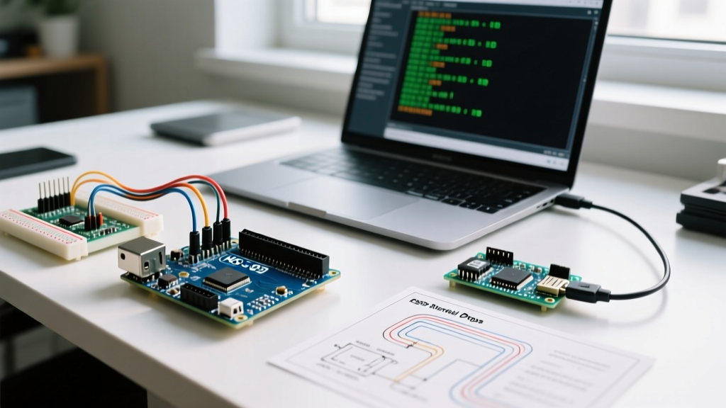

The Hidden Bottlenecks in Standard Arduino SD Logging
When engineers and makers first integrate an SD card module into a microcontroller project, the default SD.h library seems like a perfect plug-and-play solution. However, as soon as you attempt high-speed data logging—such as capturing 1kHz IMU sensor arrays, high-resolution ADC waveforms, or continuous GPS NMEA streams—the standard Arduino SD library quickly becomes a severe bottleneck. Dropped samples, buffer overflows, and unpredictable write latencies plague high-frequency applications.
The root cause is rarely the physical speed of the SD card itself. Modern UHS-I cards can sustain write speeds exceeding 40 MB/s. Instead, the bottleneck lies in the legacy software wrapper, unoptimized SPI bus configurations, and the inherent overhead of the FAT file system. In 2026, with SDXC (exFAT) cards dominating the market, relying on outdated FAT32 wrappers limits both your storage capacity and your write performance. To achieve true high-speed logging, we must bypass the abstraction layers and optimize at the filesystem and hardware bus levels.
Ditching the Wrapper: Why SdFat V2 is Mandatory
The standard Arduino SD.h library is actually a simplified wrapper around Bill Greiman’s SdFat library. While the wrapper makes basic file operations easy, it strips away the advanced performance features required for optimization. For any serious data logging, you should install the raw SdFat V2 library via the Arduino Library Manager and use it directly.
SdFat V2 introduces native exFAT support, which is critical for modern 64GB+ SDXC cards. More importantly, it exposes low-level block I/O functions, custom buffer sizing, and file pre-allocation methods that the standard wrapper hides. By instantiating SdFat sd; instead of relying on the global SD object, you unlock direct control over the SPI clock dividers and FAT chain management.
Pushing the SPI Bus: Clock Speed Tuning
The default SPI clock speed for the Arduino SD library is a conservative 4 MHz. This was chosen to ensure compatibility with long jumper wires and breadboards. However, if your SD module is soldered directly to a custom PCB or connected via short, shielded traces, you can safely push the SPI clock much higher, drastically reducing the time the MCU spends shifting bits.
Below is a performance matrix for maximum stable SPI speeds across popular microcontroller architectures when using high-quality SanDisk or Samsung UHS-I cards:
| Microcontroller | Architecture | Default Speed | Optimized Stable Speed | Max Theoretical (Short Traces) |
|---|---|---|---|---|
| ATmega328P (Uno/Nano) | AVR 8-bit | 4 MHz | 8 MHz | 8 MHz (Hardware Limit) |
| SAMD21 (Zero/MKR) | ARM Cortex-M0+ | 4 MHz | 12 MHz | 24 MHz |
| ESP32 (WROOM/WROVER) | Xtensa LX6 | 4 MHz | 20 MHz | 40 MHz |
| STM32F407 (Black Pill) | ARM Cortex-M4 | 4 MHz | 18 MHz | 36 MHz |
| Teensy 4.1 | ARM Cortex-M7 | N/A (Uses SDIO) | 24 MHz (SPI) | 48 MHz (SDIO Native) |
Implementation Tip: In SdFat, initialize the card using sd.begin(SCK_MHZ(24)) for an ESP32 or SAMD board. If you experience initialization failures or corrupted FAT tables, the issue is likely signal integrity. Add 33-ohm series resistors on the MOSI, MISO, and SCK lines close to the MCU pins to dampen high-frequency ringing caused by parasitic capacitance on the SD card module.
The Secret Weapon: File Pre-Allocation
The most common cause of dropped samples in high-speed logging is not the SPI transfer rate, but the SD card’s internal garbage collection. When you append data to a standard file, the filesystem must periodically update the File Allocation Table (FAT) to chain new clusters together. Furthermore, the SD card's internal controller may pause writes for 100ms to 300ms to perform wear-leveling and block erasure.
At a 1kHz sampling rate, a 200ms pause means 200 lost data points. To eliminate this, you must pre-allocate the file space before logging begins. Pre-allocation reserves a contiguous chain of clusters in the FAT table and signals the SD card's internal controller to prepare the NAND flash blocks, effectively disabling mid-write garbage collection.
Expert Insight: Pre-allocation transforms an unpredictable, jitter-prone write process into a deterministic, real-time stream. It is the single most impactful optimization you can make to the Arduino SD library workflow.
Pre-Allocation Code Implementation
Using SdFat, you can pre-allocate a 100MB contiguous block using the preAllocate() method. Ensure your card is freshly formatted to maximize the chances of finding a contiguous block.
#include 'SdFat.h'
SdFat sd;
FsFile logFile;

void setup() {
  sd.begin(SCK_MHZ(24));
  // Open file with O_CREAT and O_RDWR
  logFile.open('datalog.bin', O_CREAT | O_RDWR);

  // Pre-allocate 100 Megabytes (104,857,600 bytes)
  if (!logFile.preAllocate(104857600)) {
    // Handle error: Not enough contiguous space
    while(1);
  }
}
Once your logging session is complete, you must truncate the file to the actual number of bytes written using logFile.truncate() before closing it. Failing to do so will leave the file padded with garbage data up to the 100MB mark.
Cluster Size Optimization and exFAT Formatting
The physical formatting of your SD card dictates how the filesystem groups bytes into clusters. The official SD Memory Card Formatter provided by the SD Association is the only tool you should use. Windows and macOS native formatters often misalign the partition boundaries with the NAND flash erase block boundaries, causing severe write amplification and performance degradation.
- FAT32 (Cards 32GB and smaller): The default cluster size is usually 16KB or 32KB. For high-speed logging, reformat the card using a third-party tool to force a 64KB cluster size. This reduces the frequency of FAT table updates by half.
- exFAT (Cards 64GB and larger): exFAT is inherently optimized for large files and eliminates the 4GB file size limit of FAT32. SdFat V2 supports exFAT natively. The default cluster size for a 128GB card is typically 128KB, which is excellent for sequential block writes via SPI.
Advanced Technique: RAM Double-Buffering (Ping-Pong)
If you are using an MCU with ample SRAM, such as the ESP32 (520KB SRAM) or Teensy 4.1 (1MB SRAM), you should implement a double-buffering strategy. The SPI bus cannot transmit data while the MCU is actively polling sensors and writing to the primary RAM buffer.
By creating two buffers (Buffer A and Buffer B), the MCU can write sensor data into Buffer A while simultaneously using DMA (Direct Memory Access) or a secondary FreeRTOS core to flush Buffer B to the SD card. Once Buffer A is full, the pointers swap. This 'ping-pong' method completely masks the SPI write latency from the sensor polling loop, ensuring zero jitter in your timestamping.
For detailed hardware integration and wiring best practices, the Adafruit Micro SD Breakout Board Tutorial provides excellent baseline schematics, though you must modify the SPI trace lengths to support the higher clock speeds detailed in this guide.
Summary of Optimization Checklist
- Replace the default
SD.hwrapper with Bill Greiman’s SdFat V2. - Increase the SPI clock speed to the maximum stable threshold for your specific MCU (typically 12MHz - 24MHz).
- Format the SD card using the official SD Association Formatter to ensure proper NAND alignment.
- Use
preAllocate()to reserve contiguous space and prevent internal SD card garbage collection pauses. - Implement RAM double-buffering on high-memory MCUs to decouple sensor reads from SPI writes.
By applying these targeted optimizations to your Arduino SD library workflow, you can reliably achieve sustained write speeds of 1.5 MB/s to 3.0 MB/s over SPI, which is more than sufficient for multi-channel, high-frequency industrial and scientific data logging.