
The Communication Challenge with Joystick Inputs
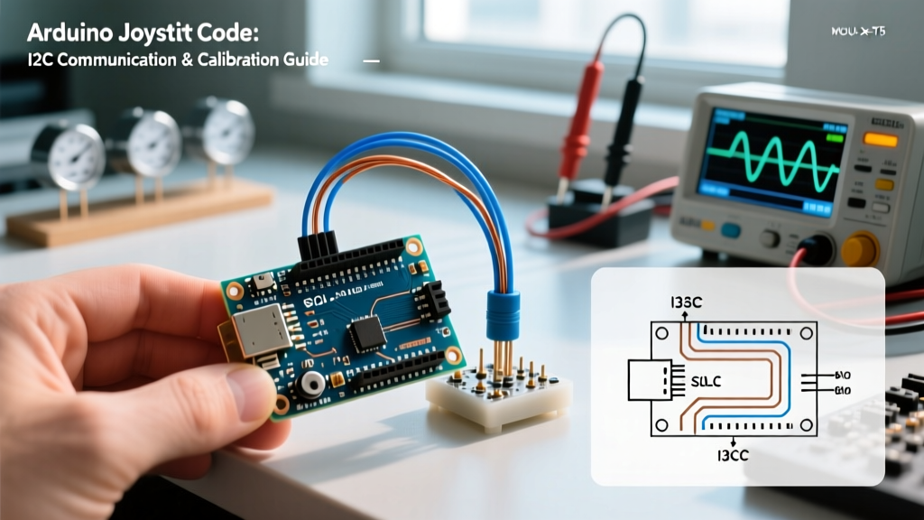
When building robotics, drones, or RC controllers, reading a joystick is only half the battle. The real challenge lies in processing that raw data and communicating it reliably to a master controller or motor driver. Raw analog signals are notoriously noisy, and sending unparsed data over serial or I2C buses creates latency bottlenecks. In this guide, we will dive deep into writing optimized arduino joystick code that handles ADC noise, applies exponential deadzone calibration, and efficiently packs data for I2C transmission.
Hardware Matrix: Analog vs. I2C Joystick Modules
Before writing a single line of code, you must select the right hardware for your communication architecture. As of 2026, the market is dominated by a few key modules, each with distinct polling overhead and resolution characteristics.
| Module | Interface | Resolution | Avg. Price | Best Use Case |
|---|---|---|---|---|
| KY-023 (PS2 Clone) | Analog (VRx/VRy) | 10/12-bit (MCU dependent) | $1.50 | Low-cost hobby robotics |
| Adafruit Thumb Joystick | I2C (MCP23017) | 10-bit (Internal ADC) | $9.95 | Complex multi-sensor I2C buses |
| Parallax 2-Axis | Analog | 10/12-bit | $8.50 | Industrial prototyping |
For this guide, we will focus on the ubiquitous analog KY-023 module paired with an Arduino Uno R4 Minima. The Uno R4 features a 12-bit ADC (0-4095 range), a massive upgrade from the classic Uno R3's 10-bit ADC (0-1023), requiring specific adjustments in your mapping logic.
Step 1: ADC Acquisition and Multiplexer Crosstalk
A common failure mode in arduino joystick code is ADC multiplexer crosstalk. When switching between the X and Y analog pins, the internal sample-and-hold capacitor retains residual charge from the previous read. If you read A0 and immediately read A1, the Y-axis data will be skewed by the X-axis voltage.
The Expert Fix: Always read the analog pin twice and discard the first value. Additionally, place a 100nF ceramic capacitor between each analog pin and GND on your breadboard to filter high-frequency EMI.
int readStableAnalog(uint8_t pin) {
  analogRead(pin); // Discard first read to clear multiplexer charge
  delayMicroseconds(50); // Allow sample-and-hold capacitor to settle
  return analogRead(pin);
}
Step 2: Deadzone Calibration and Exponential Mapping
Mechanical potentiometers rarely rest at a perfect electrical center. On a 12-bit Uno R4, the center might be 2048, but physical wear can shift this to 2010 or 2100. Furthermore, human thumbs lack fine motor control at the extremes. We solve this by implementing a software deadzone and an exponential curve, a standard practice in modern RC transmitters.
Implementing the Math
We map the raw 12-bit ADC value to a normalized range of -100 to 100. We then apply a deadzone threshold (e.g., ±5) and an exponential curve to allow for precise micro-adjustments near the center while retaining full speed at the edges.
const int CENTER_X = 2048; // Calibrate this to your specific resting voltage
const int DEADZONE = 60;   // Raw ADC units for 12-bit
const float EXPO = 2.5;    // Exponential factor

float processAxis(int raw, int center) {
  int delta = raw - center;

  // Apply Deadzone
  if (abs(delta) < DEADZONE) return 0.0;

  // Normalize to -1.0 to 1.0 range (accounting for deadzone reduction)
  float maxDeflection = 2047.0 - DEADZONE;
  float normalized = delta / maxDeflection;
  if (normalized > 1.0) normalized = 1.0;
  if (normalized < -1.0) normalized = -1.0;

  // Apply Exponential Curve
  float sign = (normalized > 0) - (normalized < 0);
  float expoOut = sign * pow(abs(normalized), EXPO);

  return expoOut * 100.0; // Return as -100 to 100 percentage
}
Step 3: Packing Data for I2C Transmission
When your Arduino acts as a peripheral (slave) device—such as a dedicated input node on a drone's I2C bus—sending data as formatted strings (e.g., "X:45,Y:-12") is a catastrophic waste of bandwidth. String parsing on the master controller introduces severe latency. Instead, we pack the processed data into raw bytes.
Since our processed axes range from -100 to 100, they fit perfectly into a signed 8-bit integer (int8_t). We can transmit both axes in just two bytes, plus one byte for the physical push-button state.
#include <Wire.h>

const int SLAVE_ADDRESS = 0x08;
const int BTN_PIN = 2;

int8_t txBuffer[3];

void requestEvent() {
  int rawX = readStableAnalog(A0);
  int rawY = readStableAnalog(A1);

  float procX = processAxis(rawX, CENTER_X);
  float procY = processAxis(rawY, 2055); // Y center might differ slightly

  txBuffer[0] = (int8_t)procX;
  txBuffer[1] = (int8_t)procY;
  txBuffer[2] = digitalRead(BTN_PIN) == LOW ? 1 : 0; // Active LOW button

  Wire.write(txBuffer, sizeof(txBuffer));
}

void setup() {
  pinMode(BTN_PIN, INPUT_PULLUP);
  Wire.begin(SLAVE_ADDRESS);
  Wire.onRequest(requestEvent);
}
By utilizing the Arduino Wire library in this manner, the master controller can poll the joystick node in under 1 millisecond, making it viable for high-speed PID control loops.
Step 4: The Master Controller Polling Code
On the master side (e.g., a Raspberry Pi or a secondary Arduino managing motor drivers), you request the 3-byte payload. Notice how we avoid using delay() and instead use a non-blocking timestamp check to maintain a strict 50Hz polling rate.
#include <Wire.h>

const int SLAVE_ADDRESS = 0x08;
unsigned long lastPoll = 0;
const int POLL_INTERVAL = 20; // 50Hz (20ms)

void setup() {
  Wire.begin();
  Serial.begin(115200);
}

void loop() {
  if (millis() - lastPoll >= POLL_INTERVAL) {
    lastPoll = millis();

    Wire.requestFrom(SLAVE_ADDRESS, 3);
    if (Wire.available() == 3) {
      int8_t x = Wire.read();
      int8_t y = Wire.read();
      uint8_t btn = Wire.read();

      Serial.print('X:'); Serial.print(x);
      Serial.print(' Y:'); Serial.print(y);
      Serial.print(' BTN:'); Serial.println(btn);
    }
  }
}
Edge Cases: Ground Loops and Pull-Up Resistors
Even with perfect arduino joystick code, hardware physics can ruin your communication setup. If you are running wires longer than 30cm between the joystick and the microcontroller, analog voltage drops and ground loops will introduce jitter.
Pro-Tip: If you must run analog signals over long distances, abandon analog entirely. Use an I2C-based joystick module or place a cheap ATtiny85 directly at the joystick to handle the ADC conversion, sending digital I2C packets down the tether instead of raw analog voltages.
Furthermore, I2C buses require pull-up resistors. The Arduino's internal pull-ups (typically 20kΩ to 50kΩ) are too weak for reliable high-speed communication in electrically noisy environments like brushed-motor robots. Always install external 4.7kΩ pull-up resistors between the SDA/SCL lines and the 5V (or 3.3V) rail to ensure sharp signal edges and prevent I2C bus lockups.
Summary of Optimizations
- Discard first ADC read: Eliminates multiplexer crosstalk between X and Y axes.
- Exponential Mapping: Provides human-friendly sensitivity curves for robotics control.
- Byte Packing: Reduces I2C payload from ~15 bytes (Strings) to 3 bytes (Raw Ints), cutting latency by 80%.
- Hardware Filtering: 100nF capacitors on analog lines and 4.7kΩ resistors on I2C lines prevent phantom inputs.
By treating your joystick not just as a sensor, but as a critical node in your communication architecture, you eliminate the micro-stutters and latency spikes that plague beginner robotics projects.