
The IDE as a Protocol Orchestrator
Most introductory tutorials treat the Arduino IDE setup as a simple "download and install" process. However, for embedded systems engineers and advanced hobbyists, the Arduino IDE (specifically the modern 2.3.x architecture) is fundamentally a complex protocol orchestrator. It does not merely compile C++ code; it manages a sophisticated stack of communication protocols to bridge the gap between your host operating system and the target microcontroller.
From fetching toolchain binaries via HTTP/HTTPS JSON schemas to negotiating USB CDC handshakes and UART bootloader sequences, understanding the underlying protocols is critical for debugging hardware failures. This guide deconstructs the Arduino IDE setup process through the lens of communication protocols, ensuring you can diagnose upload failures, serial monitor dropouts, and board manager errors with precision.
Phase 1: Board Manager JSON and HTTP Protocols
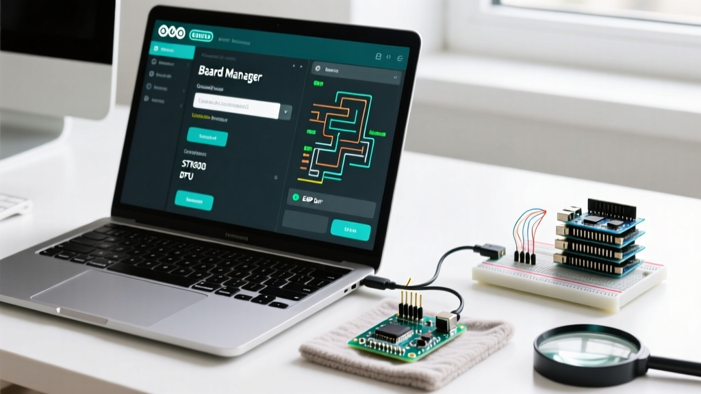
The first step in a comprehensive Arduino IDE setup for non-AVR boards (like the ESP32, RP2040, or STM32) involves the Board Manager. Under the hood, the IDE relies on a strict HTTP/HTTPS protocol to fetch and parse JSON index files. These JSON files dictate the exact GCC toolchain versions, compiler flags, and upload utilities required for a specific silicon family.
When you navigate to File > Preferences and paste a URL into the "Additional Boards Manager URLs" field, you are instructing the IDE's backend to execute an HTTPS GET request. For example, setting up the ESP32 requires the Espressif JSON index. According to the official Espressif Arduino Core documentation, the IDE parses this JSON to download the xtensa-esp32-elf toolchain and the esptool.py flashing utility.
Expert Tip: If your Arduino IDE setup fails at the "Downloading" stage with a "Connection Reset" or "403 Forbidden" error, the issue is rarely the IDE itself. It is usually an overzealous corporate firewall or antivirus software intercepting the IDE's HTTP requests to raw GitHub content delivery networks (CDNs). Whitelisting
raw.githubusercontent.comanddownloads.arduino.ccresolves 90% of these protocol-level blocks.
Phase 2: Upload Protocols and Bootloader Handshakes
Once your code is compiled, the IDE must transfer the binary to the microcontroller's flash memory. This is where the upload protocol comes into play. The IDE relies on the platform.txt and boards.txt configuration files to determine which protocol and command-line utility to invoke. Selecting the wrong board in the IDE menu results in a protocol mismatch, leading to the dreaded "programmer is not responding" error.
Below is a breakdown of the primary upload protocols utilized during the Arduino IDE setup and compilation phase:
| Upload Protocol | Target Architecture | CLI Tool Invoked | Handshake Mechanism |
|---|---|---|---|
| stk500v1 / arduino | AVR (ATmega328P, Uno) | avrdude |
DTR line toggle via 100nF capacitor to pulse the hardware RESET pin. |
| stk500v2 / wiring | AVR (ATmega2560, Mega) | avrdude |
DTR line toggle; requires precise timing to catch the bootloader window. |
| dfu / sam-ba | ARM Cortex-M (SAMD21, Due) | bossac / dfu-util |
USB CDC enumeration; relies on the 1200bps "magic baud rate" reset. |
| esptool / serial | Xtensa / RISC-V (ESP32) | esptool.py |
RTS/DTR GPIO strapping sequence to force ROM bootloader entry. |
| picotool / uf2 | RP2040 (Raspberry Pi Pico) | picotool / Mass Storage |
USB Mass Storage Device (MSC) protocol; drag-and-drop or direct binary write. |
The ESP32 RTS/DTR Strapping Protocol
When configuring your Arduino IDE setup for ESP32 development, understanding the auto-reset circuit is vital. The ESP32 does not have a dedicated hardware reset line connected to the USB-to-UART bridge (like the CP2102 or CH340). Instead, the IDE manipulates the RTS (Request to Send) and DTR (Data Terminal Ready) UART control lines. By toggling these lines in a specific microsecond sequence, the IDE pulls the ESP32's EN (Enable) and GPIO0 pins low, forcing the chip out of normal execution and into the serial bootloader. If you are designing a custom PCB, failing to route these protocol lines correctly will force you to manually hold the physical "BOOT" button during every upload.
Phase 3: UART Configuration and the 1200bps Reset Protocol
The Serial Monitor is the most used debugging tool in the Arduino ecosystem, relying on the Universal Asynchronous Receiver-Transmitter (UART) protocol. However, modern "Native USB" boards (like the Arduino Leonardo, Micro, Zero, and Teensy series) do not use a hardware UART-to-USB bridge. Instead, they use the USB Communications Device Class (CDC) protocol to emulate a serial port.
This architectural difference introduces the 1200bps Reset Protocol. Because native USB boards lack a physical DTR pin to trigger a hardware reset, the Arduino IDE uses a software-based handshake. When you click "Upload," the IDE opens the virtual COM port at exactly 1200 baud, transmits no data, and immediately closes the connection. The microcontroller's USB CDC driver is programmed to recognize 1200 baud as a "magic number." Upon detecting this specific baud rate, the MCU executes a software reset and jumps to the bootloader memory address to receive the new firmware.
For deeper insights into native USB protocols and custom bootloader configurations, the PJRC Teensy documentation provides an excellent masterclass on how USB HID and CDC protocols are multiplexed during the upload phase.
Troubleshooting Protocol Handshake Failures
Even with a perfect Arduino IDE setup, protocol-level handshakes can fail due to OS-level interference or hardware edge cases. Here is how to diagnose the most common communication breakdowns:
1. The "Board at /dev/ttyACM0 is not available" Error (Linux)
This is a USB CDC protocol permissions issue. The Linux kernel recognizes the native USB device, but the user group lacks read/write access to the serial endpoint.
The Fix: You must create a udev rule to grant permissions based on the board's Vendor ID (VID) and Product ID (PID). Create a file at /etc/udev/rules.d/99-arduino.rules and add:
SUBSYSTEM=="usb", ATTRS{idVendor}=="2341", ATTRS{idProduct}=="8036", MODE="0666"
Reload the rules with sudo udevadm control --reload-rules and physically reconnect the USB cable to force a new USB enumeration.
2. Bootloader Timeout on ATmega2560 (Windows)
The Arduino Mega uses the stk500v2 protocol, which requires the IDE to catch the bootloader within a 500-millisecond window after the DTR reset pulse. If Windows has background services (like 3D printer spoolers or CNC software like Cura) polling the COM port, the OS will "steal" the serial handshake, causing the IDE to time out.
The Fix: Close all serial-monitoring software. In the Arduino IDE, enable File > Preferences > Show Verbose Output during Upload. Watch the exact moment avrdude sends the initial sync bytes. If it fails, manually press the physical RESET button on the Mega exactly when the IDE console says "Uploading..." to manually trigger the protocol window.
3. UART Framing Errors in the Serial Monitor
If your Serial Monitor outputs garbage characters (e.g., ÿÿÿ), you are experiencing a UART framing error. This occurs when the transmitter and receiver disagree on the baud rate, parity, or stop bits. The Arduino IDE defaults to 8 data bits, no parity, and 1 stop bit (8N1). If your firmware initializes Serial.begin(115200) but the IDE Serial Monitor dropdown is set to 9600, the bit-timing alignment will fail, resulting in protocol-level data corruption. Always verify the baud rate in your setup() function matches the IDE dropdown exactly.
Advanced IDE Protocol Configurations
For users pushing the boundaries of embedded development, the official Arduino IDE documentation outlines how to pass custom compiler flags and modify the underlying protocol tools. By editing the platform.local.txt file in your board's core directory, you can override default upload speeds. For instance, increasing the ESP32 upload speed from the default 921600 baud to 2000000 baud via the upload.speed parameter can cut flashing times in half, provided your USB cable has the necessary shielding to maintain signal integrity at higher UART frequencies.
Mastering the Arduino IDE setup is not just about installing software; it is about understanding the HTTP, USB, and UART protocols that allow your PC to breathe life into silicon. By recognizing the IDE as a protocol orchestrator, you transition from a passive user to an embedded systems engineer capable of diagnosing and resolving complex communication bottlenecks.