
Understanding Arduino Hardware SPI: The Need for Speed
When you first start programming microcontrollers, reading a sensor via I2C or analog pins feels like magic. But as your projects evolve—requiring high-speed data logging, TFT displays, or fast IMU sampling—you will hit a bandwidth wall. This is where Arduino hardware SPI (Serial Peripheral Interface) becomes essential. Unlike software-based 'bit-banging' which relies on the CPU to manually toggle pins, hardware SPI utilizes a dedicated silicon peripheral inside the ATmega328P (or ARM Cortex-M4 on newer boards) to shift bits out at megahertz speeds with near-zero CPU overhead.
In this comprehensive guide, we will demystify the SPI protocol, walk through a real-world wiring scenario using the popular ADXL345 accelerometer, and write robust C++ code using modern transaction management.
The Core Anatomy of the SPI Bus
SPI is a synchronous, full-duplex communication protocol. It requires four shared lines to establish a reliable connection between a Master (your Arduino) and a Slave (the sensor). According to the SparkFun SPI Tutorial, the bus relies on the following signals:
| Signal | Arduino Pin (Uno R3) | Direction | Function |
|---|---|---|---|
| MOSI | 11 | Master → Slave | Data sent from the Arduino to the peripheral. |
| MISO | 12 | Slave → Master | Data received by the Arduino from the peripheral. |
| SCK | 13 | Master → Slave | Clock signal generated by the Master to synchronize data. |
| CS / SS | 10 (or any digital) | Master → Slave | Chip Select. Pull LOW to activate a specific slave device. |
Hardware SPI vs. Software Bit-Banging
Why go through the trouble of using specific hardware pins when you could just use the shiftOut() function on any pins? Here is a direct comparison:
- Hardware SPI: Speeds up to 8 Mbps (on a 16MHz Uno). Uses a dedicated shift register, freeing the CPU to handle math or interrupts. Requires strict adherence to designated MCU pins (or the 2x3 ICSP header).
- Software SPI: Speeds typically max out around 100-200 kbps. Consumes 100% of the CPU during transmission. Allows flexible pin mapping, which is useful if your hardware SPI pins are physically blocked by a shield.
Critical Voltage Warning: 5V vs 3.3V Logic
Beginner Trap: The classic Arduino Uno R3 operates at 5V logic. However, 90% of modern high-speed SPI sensors (like the ADXL345, BME280, or SD card modules) operate at 3.3V. Feeding 5V into a 3.3V MISO/MOSI pin will permanently destroy the sensor's silicon.
The Solution: Always use a bidirectional logic level converter (like the BSS138 or CD4050B-based modules, costing around $1.50 to $3.00). Wire the 5V side to the Arduino, the 3.3V side to the sensor, and ensure the converter's high-side and low-side reference voltages are correctly tied to the respective power rails.
Step-by-Step Wiring: Arduino Uno to ADXL345
For this tutorial, we are using the classic Arduino Uno R3 (approx. $27.00) and an ADXL345 3-axis accelerometer breakout board (approx. $5.00). The Analog Devices ADXL345 Datasheet specifies that the sensor supports SPI Mode 3 and a maximum clock speed of 5MHz.
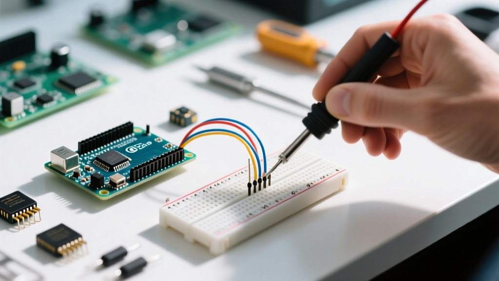
- Connect Arduino 5V to the Logic Level Converter HV pin, and 3.3V to the LV pin.
- Connect ADXL345 VCC to the Converter LV (3.3V) output.
- Connect Arduino GND to both the Converter GND and ADXL345 GND.
- Route Arduino Pins 11, 12, and 13 through the logic level converter to the ADXL345 SDA (MOSI), SDO (MISO), and SCL (SCK) pins respectively.
- Connect Arduino Pin 10 to the ADXL345 CS pin.
Decoding SPI Modes and Clock Dividers
SPI is not a single standardized protocol; it has four distinct 'Modes' based on Clock Polarity (CPOL) and Clock Phase (CPHA). If your Master and Slave are not in the same mode, data will be corrupted.
- Mode 0 (Default): Clock is LOW when idle. Data is sampled on the rising edge.
- Mode 3: Clock is HIGH when idle. Data is sampled on the rising edge. (Required by the ADXL345 and many SD cards).
Furthermore, the Official Arduino SPI Reference defines clock dividers. Since the Uno runs at 16MHz, using SPI_CLOCK_DIV4 yields a 4MHz SPI clock, which is safely under the ADXL345's 5MHz maximum.
Writing the C++ Code: Reading the Device ID
The best way to verify an SPI connection is to read a known, hard-coded register. For the ADXL345, Register 0x00 is the DEVID register, which always returns 0xE5 (229 in decimal).
Below is the robust, modern way to write SPI code using SPI.beginTransaction(). This prevents conflicts if you add an SPI SD card module later.
#include <SPI.h>

const int CS_PIN = 10;
// SPISettings defines speed, bit order, and mode
SPISettings adxlSettings(4000000, MSBFIRST, SPI_MODE3);

void setup() {
  Serial.begin(115200);
  pinMode(CS_PIN, OUTPUT);
  digitalWrite(CS_PIN, HIGH); // Deselect chip initially

  SPI.begin();
  Serial.println('Initializing ADXL345 via Hardware SPI...');

  // Read the DEVID register (0x00)
  byte deviceId = readRegister(0x00);

  if (deviceId == 0xE5) {
    Serial.print('Success! Device ID: 0x');
    Serial.println(deviceId, HEX);
  } else {
    Serial.print('Failed. Check wiring. Got: 0x');
    Serial.println(deviceId, HEX);
  }
}

void loop() {
  // Main program loop
}

byte readRegister(byte regAddress) {
  // Bit 7 must be HIGH for a read operation in ADXL345
  byte readCommand = regAddress | 0x80;
  byte result = 0;

  SPI.beginTransaction(adxlSettings);
  digitalWrite(CS_PIN, LOW); // Select the slave

  SPI.transfer(readCommand); // Send the register address
  result = SPI.transfer(0x00); // Clock in the data

  digitalWrite(CS_PIN, HIGH); // Deselect the slave
  SPI.endTransaction();

  return result;
}
Troubleshooting Common Edge Cases
Even with perfect wiring, beginners often encounter silent failures where the MISO line returns 0x00 or 0xFF. Use this checklist to debug:
1. The Floating Chip Select (CS) Pin
If you forget to set pinMode(CS_PIN, OUTPUT) and write it HIGH before calling SPI.begin(), the ATmega328P might accidentally configure itself as an SPI Slave rather than a Master. This will completely lock up the hardware SPI peripheral until the board is reset.
2. Missing the Read/Write Bit
Many SPI sensors use the most significant bit (Bit 7) of the register address to dictate the operation. As shown in the code above, you must use a bitwise OR (regAddress | 0x80) to tell the sensor you intend to read. Sending raw 0x00 will attempt a write operation, returning garbage data.
3. MISO and MOSI Swapped
Unlike I2C, SPI is not 'smart' about addressing. If you accidentally wire the Arduino's MOSI to the sensor's MOSI, the bus will physically short the outputs, potentially damaging the logic level shifter or the MCU pins. Always wire MOSI to MISO, and MISO to MOSI (Master-Out goes to Slave-In).
4. Wire Length and Capacitance
At 4MHz, SPI signals are susceptible to parasitic capacitance. If your jumper wires exceed 15-20 centimeters, the square wave clock signal will degrade into a triangle wave, causing the sensor to misread clock edges. Keep SPI traces and wires as short and direct as possible.
Final Thoughts on Bus Management
Mastering Arduino hardware SPI is a rite of passage for embedded developers. By respecting logic levels, utilizing SPISettings for transaction management, and understanding the underlying clock phases, you unlock the ability to interface with high-speed ADCs, RF transceivers like the nRF24L01+, and graphical OLED displays. Always consult the specific component datasheet for its required SPI Mode and maximum clock frequency before writing your first line of C++.