
Why SPI Remains the Gold Standard for High-Speed Sensor Interfacing
In the embedded systems landscape of 2026, Serial Peripheral Interface (SPI) remains the undisputed king of short-distance, high-throughput synchronous communication. While I2C is excellent for multi-drop networks and UART is ideal for asynchronous debugging, SPI's full-duplex nature and lack of addressing overhead make it the mandatory choice for high-speed peripherals like ADCs, DACs, and SD cards.
In this comprehensive Arduino SPI example, we will move past basic loopback tests and interface an Arduino Uno R4 Minima (currently retailing around $20) with a Microchip MCP3008 10-bit Analog-to-Digital Converter (approx. $2.50 on Mouser or DigiKey). This walkthrough covers modern SPISettings implementation, precise bitwise protocol parsing, and critical hardware edge cases that cause silent failures in the field.
Hardware Requirements and Logic Level Considerations
Before writing a single line of code, we must address the physical layer. The MCP3008 is a 5V-tolerant device, making it a perfect match for the 5V logic of the classic Arduino Uno R3 or the Uno R4 Minima. However, if you are adapting this Arduino SPI example for a 3.3V board like the Arduino Nano 33 IoT or an ESP32, you must use a logic level translator (such as the TXS0108E) or a MOSFET-based circuit (BSS138) on the MOSI, SCK, and CS lines to prevent damaging the microcontroller.
MCP3008 to Arduino Wiring Matrix
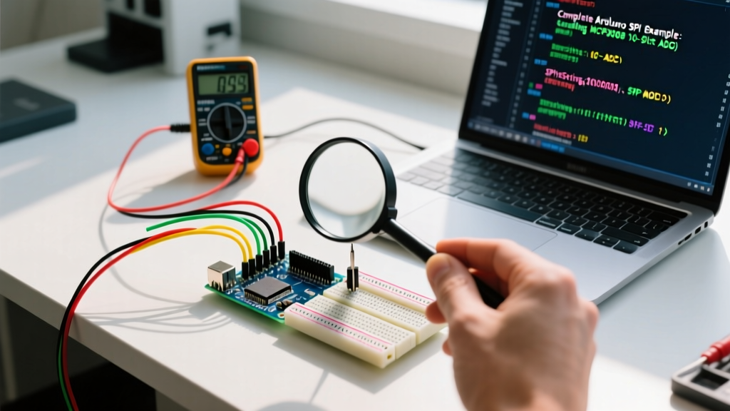
The MCP3008 comes in a 16-pin DIP package. Below is the exact wiring schematic for a standard 5V Arduino environment. Keep your SPI traces under 10 inches to prevent signal degradation and capacitive loading at higher clock speeds.
| MCP3008 Pin | Function | Arduino Uno R4 Pin | Notes |
|---|---|---|---|
| 16 (VDD) | Power Supply | 5V | Decouple with 100nF ceramic cap to GND |
| 15 (VREF) | Reference Voltage | 5V | Tie to VDD for 0-5V analog range |
| 14 (AGND) | Analog Ground | GND | Connect to digital ground at a single star point |
| 9 (DGND) | Digital Ground | GND | Must share common ground with Arduino |
| 13 (CLK) | SPI Clock (SCK) | Pin 13 (SCK) | Max 3.6 MHz at 5V; we will use 1 MHz |
| 12 (DOUT) | Data Out (MISO) | Pin 12 (MISO) | Master In, Slave Out |
| 11 (DIN) | Data In (MOSI) | Pin 11 (MOSI) | Master Out, Slave In |
| 10 (CS/SHDN) | Chip Select | Pin 10 (SS) | Active LOW. Do not leave floating! |
Modern SPI Protocol: Why SPISettings is Mandatory
If you are reading legacy tutorials from 2015, you will see SPI.setClockDivider(SPI_CLOCK_DIV16). Do not use this in 2026. Modern Arduino cores utilize the SPISettings class within a transaction block. This is critical for RTOS environments or projects utilizing interrupts, as it temporarily locks the SPI bus configuration, preventing other libraries (like an SD card or TFT display) from corrupting your clock speed or bit order mid-transfer.
Expert Tip: The MCP3008 datasheet specifies a maximum clock speed of 3.6 MHz at 5V. However, breadboard parasitic capacitance can cause signal ringing. We will configure our
SPISettingsto 1 MHz (1000000) to guarantee rock-solid data integrity on standard solderless breadboards.
For a deeper understanding of bus arbitration, refer to the official Arduino SPI Reference Documentation.
Deconstructing the MCP3008 Bitwise Command
Unlike I2C, SPI does not have a standardized register map. Every manufacturer defines their own byte sequence. According to the Microchip MCP3008 Datasheet, reading a single-ended analog channel requires the master to send a specific 5-bit command sequence across the MOSI line, while simultaneously reading the returning bits on MISO.
- Bit 1 (Start Bit): Must be
1. - Bit 2 (SGL/DIFF):
1for Single-Ended,0for Differential. - Bits 3-5 (Channel):
000to111(Channels 0-7).
To send this efficiently in C++, we split it across two bytes. We send 0x01 as the first byte to trigger the start bit. The second byte is constructed using bitwise OR and shift operations: (0x08 | channel) << 4. This elegantly packs the single-ended flag and the channel number into the correct positions.
The Complete Arduino SPI Example Code
Copy and paste this optimized, non-blocking code into your Arduino IDE. It reads Channel 0, parses the 10-bit result, and calculates the actual voltage.
#include <SPI.h>

// Define the Chip Select pin for the MCP3008
const int CHIP_SELECT_PIN = 10;

// Configure SPI: 1MHz Clock, Most Significant Bit First, SPI Mode 0 (CPOL=0, CPHA=0)
SPISettings mcp3008Settings(1000000, MSBFIRST, SPI_MODE0);

void setup() {
  Serial.begin(115200);
  while (!Serial) { delay(10); } // Wait for serial monitor (native USB boards)

  pinMode(CHIP_SELECT_PIN, OUTPUT);
  digitalWrite(CHIP_SELECT_PIN, HIGH); // Deselect the ADC initially

  SPI.begin();
  Serial.println("MCP3008 SPI ADC Initialized.");
}

void loop() {
  int adcValue = readMCP3008(0); // Read Channel 0
  float voltage = adcValue * (5.0 / 1023.0);

  Serial.print("CH0 Raw: ");
  Serial.print(adcValue);
  Serial.print(" | Voltage: ");
  Serial.print(voltage, 3);
  Serial.println(" V");

  delay(250); // 4Hz sampling rate
}

int readMCP3008(uint8_t channel) {
  if (channel > 7) return -1; // Safety check

  byte config_bits = 0x01;               // Start bit
  byte channel_bits = (0x08 | channel) << 4; // SGL/DIFF + Channel

  SPI.beginTransaction(mcp3008Settings);
  digitalWrite(CHIP_SELECT_PIN, LOW);    // Assert Chip Select

  SPI.transfer(config_bits);             // Send Start bit
  byte b1 = SPI.transfer(channel_bits);  // Send Config, receive Null + MSBs
  byte b2 = SPI.transfer(0x00);          // Send dummy byte, receive LSBs

  digitalWrite(CHIP_SELECT_PIN, HIGH);   // Deassert Chip Select
  SPI.endTransaction();

  // Mask the first byte to keep only the 2 MSBs, shift left 8, and combine with b2
  int adcResult = ((b1 & 0x03) << 8) | b2;
  return adcResult;
}
Troubleshooting Common SPI Failure Modes
Even with perfect code, hardware realities can cause erratic behavior. If your serial monitor outputs 1023, 0, or random noise, diagnose the issue using this framework:
1. MISO and MOSI Swap
The most frequent error in SPI wiring is confusing the Master/Slave perspective. Remember: MOSI on the Arduino must connect to DIN (Data In) on the MCP3008. MISO on the Arduino connects to DOUT (Data Out). If you get a constant reading of 0 or 1023 regardless of input voltage, swap these two wires.
2. Floating Analog Inputs
The MCP3008 has high-impedance inputs. If you leave an unconnected channel floating, it will act as an antenna, picking up 50/60Hz mains hum and causing crosstalk on adjacent channels. Always tie unused analog inputs to AGND via a 10kΩ resistor, or place a 100nF ceramic capacitor between the active analog input and GND to create a low-pass filter that stabilizes the sample-and-hold circuit.
3. Chip Select (CS) Left Floating
Never leave the CS/SHDN pin (Pin 10) unconnected, even if you are only using one SPI device. A floating CS pin can randomly dip LOW due to electromagnetic interference, causing the MCP3008 to hijack the MISO line and corrupt data from other SPI peripherals sharing the bus. Always use digitalWrite(CS_PIN, HIGH) in your setup() function before calling SPI.begin().
Advanced Optimization: DMA and Interrupts
For audio sampling or high-frequency vibration analysis requiring 10kHz+ sampling rates, standard polling via loop() will fail due to interrupt latency. In advanced 2026 architectures (like the Arduino Portenta H7 or Teensy 4.1), you should pair this Arduino SPI example with Direct Memory Access (DMA). DMA allows the SPI peripheral to push ADC data directly into a RAM buffer without CPU intervention. While the Uno R4 Minima supports basic DMA via the Renesas FSP (Flexible Software Package) core, implementing it requires bypassing the standard SPI.h library and writing directly to the hardware registers. For a primer on SPI bus architectures and signal integrity, review the SparkFun SPI Tutorial.
Summary
Mastering SPI requires more than just copying wiring diagrams; it demands an understanding of clock phases, bitwise command structures, and bus arbitration. By utilizing SPISettings, properly managing the Chip Select line, and filtering your analog inputs, this MCP3008 Arduino SPI example provides a robust, production-ready foundation for any high-resolution data acquisition project.