
Understanding Joystick Communication Protocols
When developing reliable arduino code for joystick integration, the first engineering hurdle is understanding the physical communication layer between the mechanical module and your microcontroller. Whether you are building a robotic arm controller, a custom gamepad, or a PTZ camera rig, the way your Arduino polls positional data dictates the responsiveness and accuracy of your entire system.
Most hobbyist and prototyping builds rely on one of two communication architectures: the analog voltage divider method (using standard KY-023 / PS2 modules) or digital bus communication (using I2C or SPI gaming joysticks). Below is a technical comparison to help you select the right protocol for your 2026 project requirements.
| Feature | KY-023 Analog Module | I2C Digital Joystick (e.g., Adafruit) |
|---|---|---|
| Communication Protocol | Analog Voltage (ADC) | I2C (Digital Bus) |
| Typical Cost (2026) | $1.50 - $3.00 | $14.95 - $19.99 |
| Wiring Complexity | 5 wires (VCC, GND, X, Y, SW) | 4 wires (VCC, GND, SDA, SCL) |
| Microcontroller Load | High (ADC polling takes ~100µs) | Low (Interrupt or fast bus read) |
| Best Use Case | Simple RC controls, basic robotics | Multiplayer gamepads, I2C daisy-chaining |
Wiring the KY-023 for ADC Communication
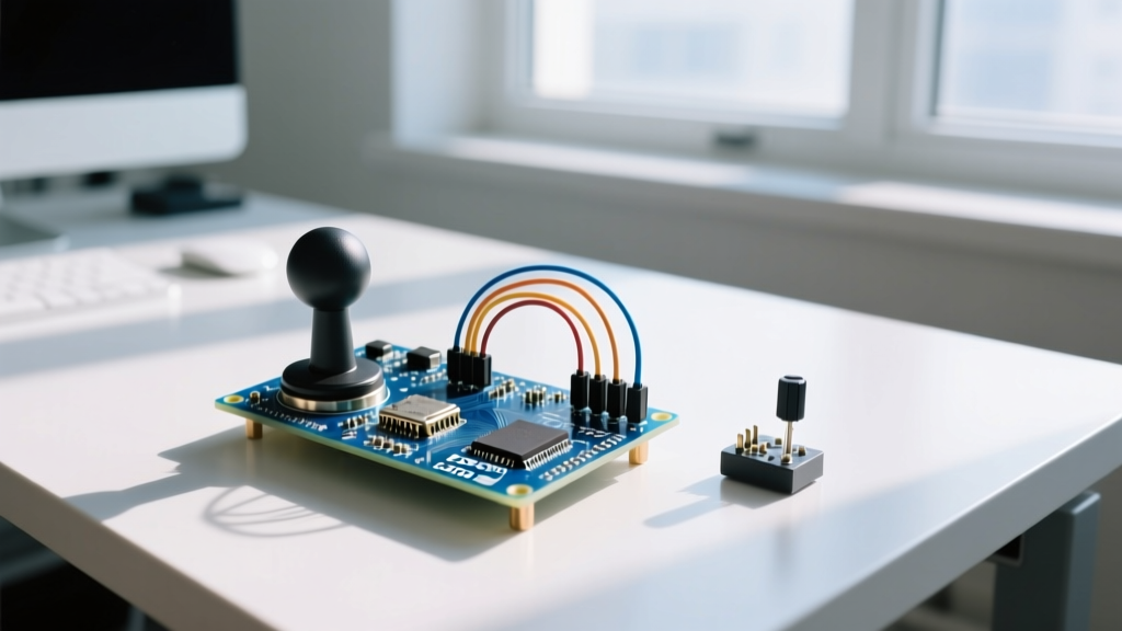
The ubiquitous KY-023 joystick module houses two 10kΩ potentiometers and a momentary pushbutton. It communicates position by outputting a variable voltage between 0V and VCC. According to the SparkFun Joystick Hookup Guide, proper wiring is critical to avoid floating analog pins, which introduce severe electromagnetic interference (EMI) noise into your readings.
Standard 5V Arduino (Uno/Nano/Mega) Pinout
- GND → Arduino GND
- +5V → Arduino 5V
- VRx → Arduino A0 (X-axis analog input)
- VRy → Arduino A1 (Y-axis analog input)
- SW → Arduino D2 (Digital pin with internal pull-up)
⚠ CRITICAL ESP32 / 3.3V WARNING: The KY-023 is designed for 5V logic. If you are using an ESP32, Raspberry Pi Pico, or Arduino Zero, the GPIO pins are strictly limited to 3.3V. Feeding 5V into an ESP32 ADC pin will permanently degrade the SoC. Furthermore, the ESP32's ADC is notoriously non-linear near the 0V and 3.3V rails. You must use a voltage divider (two 10kΩ resistors) to step the joystick output down to a safe 0-2.5V range before writing your arduino code for joystick mapping.
Optimized Arduino Code for Joystick Input
Beginner tutorials often map raw ADC values (0-1023) directly to motor speeds. This is a critical flaw. Mechanical springs in joysticks suffer from center-point variance; a module might rest at 505 instead of a perfect 512. If you map this directly, your robot will slowly drift even when the joystick is untouched. Professional arduino code for joystick control requires a software deadzone and center-calibration.
The following code implements a non-blocking read, a dynamic deadzone, and button debouncing without using the blocking delay() function, ensuring your main loop remains responsive for PID controllers or wireless communication tasks.
// Pin Definitions
const int PIN_X = A0;
const int PIN_Y = A1;
const int PIN_SW = 2;

// Calibration & Deadzone Constants
const int CENTER_VAL = 512; // Nominal center, adjust after testing
const int DEADZONE = 25;    // Ignore micro-drifts within +/- 25 of center

// Button Debounce Variables
unsigned long lastDebounceTime = 0;
unsigned long debounceDelay = 50;
int buttonState = HIGH;
int lastReading = HIGH;

void setup() {
  Serial.begin(115200);
  pinMode(PIN_SW, INPUT_PULLUP); // Use internal pull-up for switch

  // Optional: Use internal 1.1V reference for stability if VCC sags
  // analogReference(INTERNAL); // Requires voltage divider on joystick VCC
}void loop() {
  // 1. Read Raw Analog Values
  int rawX = analogRead(PIN_X);
  int rawY = analogRead(PIN_Y);

  // 2. Apply Deadzone Logic
  if (abs(rawX - CENTER_VAL) < DEADZONE) rawX = CENTER_VAL;
  if (abs(rawY - CENTER_VAL) < DEADZONE) rawY = CENTER_VAL;

  // 3. Map to Usable Range (-100 to 100 for Motor PWM control)
  int mappedX = map(rawX, 0, 1023, -100, 100);
  int mappedY = map(rawY, 0, 1023, -100, 100);

  // 4. Non-Blocking Button Read
  int currentReading = digitalRead(PIN_SW);
  if (currentReading != lastReading) {
    lastDebounceTime = millis();
  }
  if ((millis() - lastDebounceTime) > debounceDelay) {
    if (currentReading != buttonState) {
      buttonState = currentReading;
      if (buttonState == LOW) {
        Serial.println('Button Pressed!');
      }
    }
  }
  lastReading = currentReading;

  // 5. Output Data (Throttled to 20Hz to prevent Serial buffer flooding)
  static unsigned long lastPrint = 0;
  if (millis() - lastPrint >= 50) {
    Serial.print('X:'); Serial.print(mappedX);
    Serial.print(' | Y:'); Serial.println(mappedY);
    lastPrint = millis();
  }
}
As noted in the official Arduino AnalogRead Reference documentation, an analogRead() call takes approximately 100 microseconds. Reading two axes sequentially takes 200µs. While negligible for basic tasks, if you are polling 4 joysticks for a quad-stick RC transmitter, this ADC latency can bottleneck high-frequency RF communication loops (like NRF24L01+). In those scenarios, consider multiplexing or switching to I2C digital joysticks.
Advanced I2C Joystick Communication
If your project requires daisy-chaining multiple controllers or you want to offload ADC processing from the main microcontroller, I2C digital joysticks (such as those utilizing an integrated MCP23017 I/O expander or dedicated Hall-effect sensors) are the superior choice.
I2C Setup Workflow
- Address Resolution: Most I2C joysticks default to
0x48or0x40. Always run an I2C Scanner script first to verify the bus address and ensure your pull-up resistors (typically 4.7kΩ) are correctly seated. - Polling Rate: Unlike analog reads, I2C requires a handshake. Polling an I2C joystick at 1000Hz will saturate a standard 100kHz I2C bus. Limit your polling rate to 125Hz (every 8ms) for smooth, jitter-free input.
- Library Integration: Utilize the
Wire.hlibrary to request bytes. Typically, Byte 0 represents the X-axis, Byte 1 the Y-axis, and Byte 2 the button states.
For comprehensive bus troubleshooting and timing diagrams, refer to the Arduino Reading Analog Input and I2C Guidelines.
Real-World Edge Cases & Troubleshooting
Even with perfect arduino code for joystick mapping, hardware realities will introduce bugs. Here is how to diagnose the three most common field failures:
- VCC Sag Drift: If your joystick shares a 5V rail with high-draw components (like servos or DC motors), the VCC might drop from 5.0V to 4.6V under load. Because the Arduino's default ADC reference is tied to VCC, the ratio technically remains the same. However, if your joystick is powered by a clean 5V source while the Arduino's 5V rail sags, your analog readings will shift wildly. Fix: Power the joystick from the same sagging rail, or use
analogReference(INTERNAL)with a voltage divider. - ADC Cross-Talk (Ghosting): When reading A0 and A1 sequentially, the internal sample-and-hold capacitor in the ATmega328P doesn't fully discharge between reads, causing the X-axis to 'bleed' into the Y-axis. Fix: Read the analog pin twice in a row and discard the first reading.
- Mechanical Spring Fatigue: Over 6-12 months of heavy use, the physical centering springs weaken. Your
CENTER_VAL = 512hardcoded constant will cause drift. Fix: Implement a 'Calibration Mode' in your code where the user holds a button on startup, and the Arduino records the resting analog values as the new center baseline.
Frequently Asked Questions
Can I use an analog joystick to generate interrupts?
No. Analog voltage changes cannot trigger hardware interrupts on standard Arduinos. If you need event-driven joystick input without polling, you must use a digital joystick with an INT pin or implement a timer-based interrupt in your code to sample the ADC at fixed intervals.
Why is my mapped output jittering between -1 and 1 at rest?
This is ADC quantization noise combined with minor thermal fluctuations in the 10kΩ potentiometer carbon track. Expanding your software DEADZONE constant from 15 to 30 will eliminate this micro-jitter without noticeably impacting user control resolution.