
Understanding the KY-023 Joystick Module
When learning beginner programming for microcontrollers, mastering analog inputs is a critical milestone. As of 2026, the KY-023 dual-axis joystick module remains the undisputed champion for entry-level projects. Retailing between $1.50 and $2.50 for a five-pack on major electronics marketplaces, it offers an accessible gateway to robotics, camera gimbals, and game controllers.
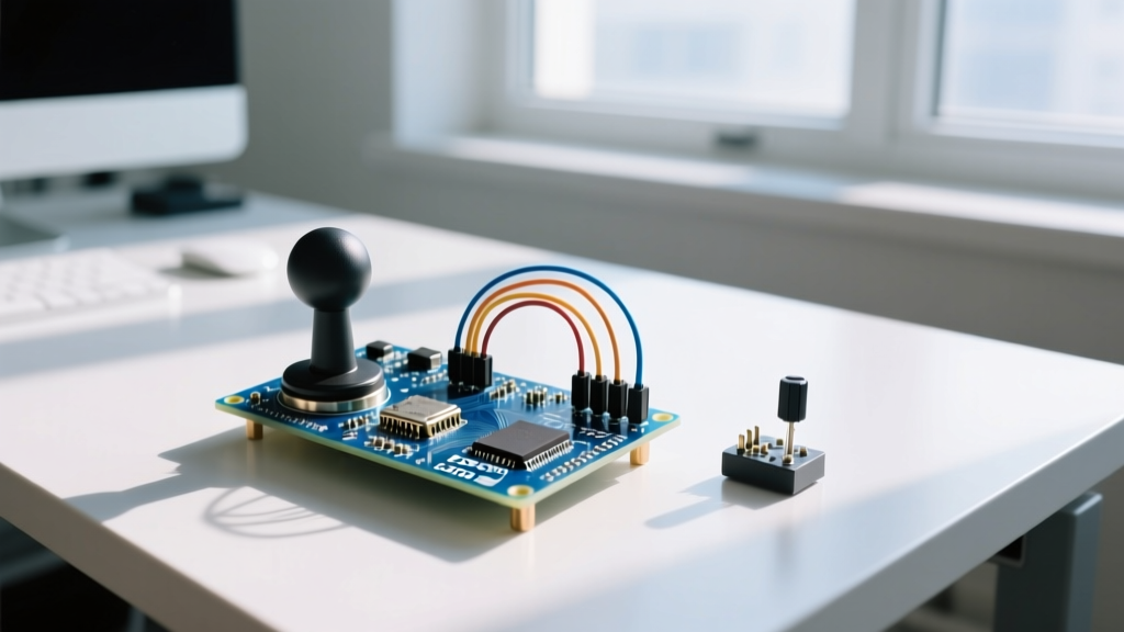
Internally, the KY-023 mimics the thumbsticks found on legacy PS2 controllers. It utilizes two independent 10kΩ potentiometers (one for the X-axis, one for the Y-axis) arranged in a gimbal mechanism. Additionally, it features a momentary tactile switch activated when you press down on the shaft. Understanding this hardware layout is the first step to writing reliable joystick code for Arduino.
Wiring the Joystick to an Arduino Uno
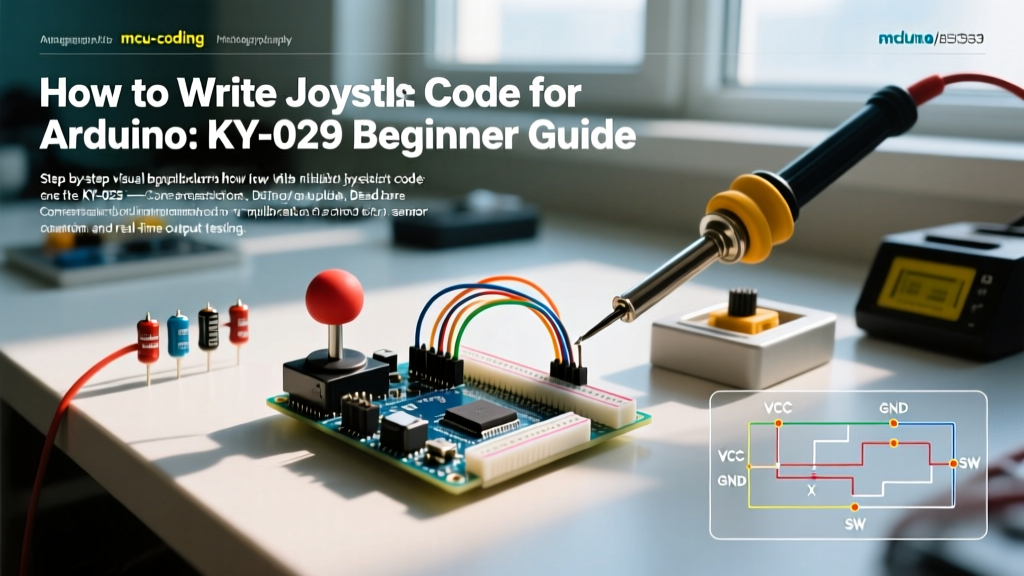
Before writing any code, we must establish a clean physical connection. The KY-023 operates natively at 5V logic, making it perfectly suited for the Arduino Uno, Nano, and Mega. If you are using a 3.3V board like the Arduino Nano 33 IoT or an ESP32, you must use a logic level shifter or a voltage divider to prevent damaging the ADC pins.
| KY-023 Pin | Arduino Uno Pin | Function & Notes |
|---|---|---|
| GND | GND | Common Ground |
| +5V | 5V | Power Supply (Do not use 3.3V on a 5V board) |
| VRx | A0 | X-Axis Analog Output (0-1023) |
| VRy | A1 | Y-Axis Analog Output (0-1023) |
| SW | D2 | Digital Switch (Active LOW) |
Expert Tip: Notice we are connecting the SW (switch) pin to Digital Pin 2. In our code, we will utilize the microcontroller's internal pull-up resistor. This eliminates the need for an external 10kΩ resistor on your breadboard, keeping your wiring clean and reducing points of failure.
The Core Joystick Code for Arduino
Below is a robust, production-ready starter sketch. Unlike basic tutorials that simply print raw values to the serial monitor, this code includes foundational calibration variables and state tracking for the push-button.
// Pin Definitions
const int PIN_VRX = A0;
const int PIN_VRY = A1;
const int PIN_SW  = 2;

// Calibration Variables (Adjust these based on your specific module)
const int X_CENTER = 512;
const int Y_CENTER = 512;
const int DEADZONE = 15;

int xValue = 0;
int yValue = 0;
int swState = 0;

void setup() {
  Serial.begin(9600);
  // Enable internal pull-up resistor for the switch pin
  // See: https://docs.arduino.cc/language-reference/en/variables/constants/constants/
  pinMode(PIN_SW, INPUT_PULLUP);
}

void loop() {
  // Read raw analog values
  xValue = analogRead(PIN_VRX);
  yValue = analogRead(PIN_VRY);
  swState = digitalRead(PIN_SW);

  // Apply Deadzone Logic
  if (abs(xValue - X_CENTER) < DEADZONE) xValue = X_CENTER;
  if (abs(yValue - Y_CENTER) < DEADZONE) yValue = Y_CENTER;

  // Map X and Y to a more usable range (-100 to 100)
  int mappedX = map(xValue, 0, 1023, -100, 100);
  int mappedY = map(yValue, 0, 1023, -100, 100);

  // Output to Serial Monitor
  Serial.print("X: ");
  Serial.print(mappedX);
  Serial.print(" | Y: ");
  Serial.print(mappedY);
  Serial.print(" | Button: ");
  Serial.println(swState == LOW ? "PRESSED" : "RELEASED");

  delay(50); // Small delay for readability
}
Solving the Drift Problem: Why Deadzones Matter
The most common failure mode beginners encounter when writing joystick code for Arduino is mechanical drift. Because the KY-023 uses mass-produced carbon-track potentiometers, the physical center point rarely outputs a perfect digital value of 512. It might rest at 504, 518, or even 495.
If you map a resting value of 504 directly to a motor controller, your robot will slowly veer to the left even when the joystick is untouched. This is where the DEADZONE logic in the code above becomes critical.
How to Calibrate Your Specific Joystick
- Upload a basic AnalogInOutSerial sketch to read raw values.
- Open the Serial Plotter in the Arduino IDE.
- Let the joystick sit completely untouched for 10 seconds.
- Record the average resting values for X and Y.
- Update the
X_CENTERandY_CENTERconstants in your code with these exact numbers.
Practical Application: Mapping to Servo Motors
Reading raw values is only half the battle. In 90% of beginner projects, the ultimate goal is to control a physical actuator, such as an SG90 micro servo or a pan-tilt camera bracket. The Arduino map() function is your best friend here.
Standard hobby servos accept pulse widths corresponding to angles between 0° and 180°. However, feeding raw 0-1023 values into a servo will cause it to jitter violently or stall. Here is how you translate the -100 to 100 mapped values into smooth servo movements:
#include <Servo.h>
Servo panServo;
Servo tiltServo;

void setup() {
  panServo.attach(9);
  tiltServo.attach(10);
}

void loop() {
  // Assume mappedX and mappedY are calculated as shown in the core code
  // We map the -100 to 100 range to the servo's 0 to 180 degree range
  int servoX = map(mappedX, -100, 100, 0, 180);
  int servoY = map(mappedY, -100, 100, 0, 180);

  // Constrain ensures we never send invalid pulse widths to the servo
  panServo.write(constrain(servoX, 0, 180));
  tiltServo.write(constrain(servoY, 0, 180));
}
By utilizing constrain(), you protect the servo's internal potentiometer from receiving out-of-bounds commands that could strip the plastic gears. This defensive programming habit is a hallmark of experienced firmware developers.
Troubleshooting Analog Noise and Jitter
If your serial monitor shows the X and Y values jumping erratically (e.g., 510, 515, 508, 512) while the joystick is stationary, you are experiencing ADC (Analog-to-Digital Converter) noise. According to Arduino's official analogRead documentation, the ATmega328P ADC is highly sensitive to electromagnetic interference and power rail fluctuations.
Hardware Fixes for Noise
- Bypass Capacitors: Solder a 0.1µF ceramic capacitor directly across the VCC and GND pins on the KY-023 breakout board. This filters out high-frequency noise from the power supply.
- Twisted Pair Wiring: If your joystick is mounted more than 6 inches away from the Arduino, twist the analog signal wires together with the ground wire to minimize inductive coupling.
Software Fixes: Moving Average Filter
If hardware modifications aren't possible, implement a simple moving average in your code. Instead of taking a single analogRead(), take 8 rapid readings, sum them, and divide by 8. This smooths out transient voltage spikes at the cost of a few milliseconds of latency, which is imperceptible in most human-interface applications.
Frequently Asked Questions
Can I use the KY-023 with an ESP32?
Yes, but with a major caveat. The ESP32 operates at 3.3V logic. Feeding 5V from the KY-023 into an ESP32 GPIO pin will permanently damage the microcontroller. You must power the KY-023 with 3.3V (which reduces the analog resolution slightly) or use a bidirectional logic level shifter.
Why does my push-button read HIGH when released?
This is the expected behavior when using INPUT_PULLUP. The internal resistor pulls the pin to 5V (HIGH). When you press the button, it connects the pin directly to GND, pulling it LOW. Always write your logic to trigger on LOW for the SW pin.