
The Hidden Cost of delay() in Production Firmware
When engineers and hobbyists first search for arduino code for flashing led circuits, they are almost universally met with the standard delay() function. While adequate for a quick classroom demonstration or a basic breadboard test, relying on delay() in 2026 for production-grade IoT devices, sensor fusion arrays, or real-time telemetry is a critical architectural flaw. The delay() function is inherently blocking; it halts the CPU's main loop, forcing the microcontroller into a busy-wait state where it cannot process incoming I2C data, read SPI sensors, or service critical external interrupts.
Watchdog Timers and Missed Interrupts
In industrial environments, firmware must remain responsive. If your flashing LED routine uses a delay(2000) to hold an indicator on for two seconds, any incoming UART serial data or hardware interrupt exceeding the buffer limit will be dropped. Furthermore, robust production firmware utilizes the hardware Watchdog Timer (WDT) to recover from infinite loop lockups. If your WDT is configured for a 1-second timeout and your LED flash routine blocks execution for 2 seconds, the microcontroller will endlessly reset, bricking the device in the field.
Level 1: Bulletproof millis() and the 49-Day Rollover Bug
The first step in writing professional arduino code for flashing led indicators is adopting a non-blocking state machine using the millis() function. According to the Arduino Time Documentation, millis() returns the number of milliseconds since the board began running the current program. However, naive implementations often fall victim to the infamous 49.7-day rollover bug, where the 32-bit unsigned long integer maxes out at 4,294,967,295 and resets to zero.
To write rollover-safe code, you must never use addition to predict the future timestamp. Instead, use unsigned subtraction to measure the elapsed time interval.
// Rollover-Safe Non-Blocking LED Flash
unsigned long previousMillis = 0;
const long interval = 1000;
bool ledState = LOW;

void setup() {
  pinMode(13, OUTPUT);
}

void loop() {
  unsigned long currentMillis = millis();

  // CORRECT: Unsigned subtraction handles rollover automatically
  if (currentMillis - previousMillis >= interval) {
    previousMillis = currentMillis;
    ledState = !ledState;
    digitalWrite(13, ledState);
  }

  // CPU is now free to handle I2C, SPI, and UART tasks
  readTelemetrySensors();
}
Incorrect Pattern to Avoid: if (currentMillis >= previousMillis + interval). When previousMillis + interval exceeds the 32-bit limit, it overflows to a small number, causing the LED to flash erratically or lock up entirely for weeks.
Level 2: Hardware Timers for Jitter-Free Pulsing
While millis() frees the CPU, it is still subject to software jitter. If a high-priority interrupt (like an I2C slave receive event) fires exactly when your loop() is evaluating the millis() condition, the LED toggle will be delayed by several microseconds. For standard visual indicators, this is invisible. But if you are flashing an IR LED for a 38kHz carrier signal, or pulsing a laser diode for a LiDAR time-of-flight sensor, software jitter will corrupt your data.
To achieve nanosecond-accurate pulsing, you must offload the flashing to the microcontroller's hardware timers. Below is a comparison of flashing techniques based on the classic ATmega328P architecture detailed in the Microchip ATmega328P Product Page.
| Technique | Max Frequency | Jitter | CPU Overhead | Best Use Case |
|---|---|---|---|---|
| delay() | ~500 Hz | High | 100% (Blocking) | Basic classroom tutorials |
| millis() Polling | ~5 kHz | Medium (µs) | Low (1% per loop) | Visual status indicators, beacons |
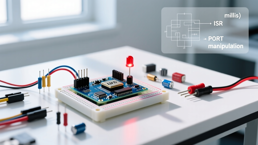
| Timer Interrupt (ISR) | ~50 kHz | Low (ns) | Medium (Context switching) | Software PWM, multi-LED multiplexing |
| Hardware CTC Mode | 8 MHz | Zero | 0% (Hardware handled) | IR carriers, LiDAR pulsing, high-speed comms |
By configuring Timer1 in Clear Timer on Compare (CTC) mode, the hardware automatically toggles the Output Compare (OC1A) pin without any CPU intervention. This guarantees a mathematically perfect 50% duty cycle square wave, entirely immune to background code execution times.
Level 3: Direct Port Manipulation (Sub-Microsecond Precision)
The standard digitalWrite() function is notoriously slow. On a 16MHz AVR-based Arduino Uno R3, digitalWrite() takes approximately 3.5 to 4 microseconds to execute because it must perform pin mapping lookups, disable interrupts, and manipulate the registers safely. If you need to flash an LED array in a tight multiplexing loop or generate precise bit-banged protocols, this overhead is unacceptable.
ATmega328P vs Renesas RA4M1 Register Mapping
Direct port manipulation bypasses the Arduino abstraction layer, writing directly to the microcontroller's memory-mapped I/O registers. On the classic ATmega328P, setting Pin 13 (PB5) HIGH requires a single bitwise OR operation:
// Set DDRB (Data Direction Register) to output in setup()
DDRB |= (1 << DDB5);

// Toggle PORTB in 62.5 nanoseconds (1 clock cycle at 16MHz)
PORTB ^= (1 << PORTB5);
However, the landscape of 2026 heavily features the Arduino Uno R4 Minima, powered by the 32-bit Renesas RA4M1 ARM Cortex-M4 running at 48MHz. As noted in the Arduino Uno R4 Minima Hardware Docs, the register architecture is vastly different. The RA4M1 utilizes Port Function Select (PFS) registers and 16-bit PORT/PDR mappings. Direct manipulation on the R4 requires targeting the specific memory addresses defined in the Renesas Flexible Software Package (FSP), allowing for toggling speeds in the low nanosecond range, vastly outpacing legacy 8-bit AVRs.
Real-World Failure Modes & EMI Mitigation
Writing the firmware is only half the battle. When your advanced arduino code for flashing led arrays transitions from the IDE to physical hardware, high-speed switching introduces severe electrical engineering challenges.
- Parasitic Inductance and Ringing: When using direct port manipulation to switch a high-power LED (like a Cree XLamp XP-E2 drawing 1A) via a logic-level MOSFET (e.g., IRLZ44N), the nanosecond rise times will cause severe voltage ringing on the PCB traces due to parasitic inductance. This ringing can exceed the MOSFET's Vgs threshold, causing phantom flashing or catastrophic gate oxide breakdown.
- EMI Radiation: Fast edge rates act as broadband RF transmitters. If your device must pass FCC Part 15 Class B emissions testing, you must insert a 33Ω to 100Ω series gate resistor between the Arduino pin and the MOSFET gate to intentionally slow the rise time (slew rate control).
- Brownout Resets: Flashing high-current LED strips simultaneously causes instantaneous voltage sag on the 5V rail. If the sag drops below the microcontroller's Brownout Detection (BOD) threshold (typically 2.7V or 4.3V), the MCU will reset. Always isolate high-power LED drivers using an optocoupler (like the PC817, costing roughly $0.15 in bulk) and provide local bulk capacitance (e.g., 470µF low-ESR electrolytic) near the LED driver.
Expert Tip: Never rely on the microcontroller's internal 5V regulator to source current for more than a single standard 20mA indicator LED. For multi-LED arrays, always use a dedicated external buck converter (like the LM2596 or MP1584) and switch the low-side ground path using an N-channel MOSFET to ensure clean, high-current pulsing without browning out the MCU logic.
By graduating from blocking delays to non-blocking state machines, leveraging hardware timers for jitter-free signals, and respecting the physical realities of high-speed EMI, you transform a simple flashing LED script into robust, production-ready embedded firmware.