
The Core Challenge: Mechanical Bounce in Digital Communication
When developing reliable button code arduino implementations for communication networks, the physical reality of mechanical switches often undermines software logic. A standard tactile switch does not close cleanly; the metal contacts physically bounce against each other for 1 to 5 milliseconds before settling. If your microcontroller is polling the pin or transmitting raw states over UART, this bounce translates into dozens of phantom triggers, flooding your communication bus and corrupting downstream logic.
Why Polling Fails in High-Speed UART Networks
In a basic polling loop using digitalRead(), the MCU checks the pin state sequentially. If a bounce occurs while the MCU is busy handling a UART transmission or processing an I2C sensor array, the state change is missed entirely. Conversely, if the MCU catches the bounce, it might transmit five separate "button pressed" packets over the serial line at 115200 baud. In 2026, where edge-computing nodes and IoT gateways expect clean, discrete event packets, sending raw, un-debounced poll data is a critical architectural flaw.
Hardware Selection: Choosing the Right Switch for 2026 MCU Projects
Before writing a single line of code, you must select the appropriate input mechanism. The choice of switch dictates your debouncing strategy and hardware filtering requirements. Below is a comparison of standard input components used in modern MCU communication setups.
| Component Type | Specific Model | Avg. Cost (2026) | Bounce Time | Best Use Case |
|---|---|---|---|---|
| Tactile Switch | Omron B3F-4105 | $0.12 | 1 - 5 ms | Low-cost consumer interfaces, breadboard prototyping |
| Mechanical Keyboard Switch | Cherry MX Blue | $0.85 | 2 - 6 ms | High-end industrial control panels, heavy tactile feedback |
| Hall Effect Sensor | Allegro A3144 | $0.45 | 0 ms (Solid State) | High-vibration environments, magnetic limit switches |
| Capacitive Touch IC | TTP223-BA6 | $0.18 | 0 ms (Internal Logic) | Sealed enclosures, waterproof IoT nodes |
Writing Robust Button Code Arduino: Interrupts vs. Polling
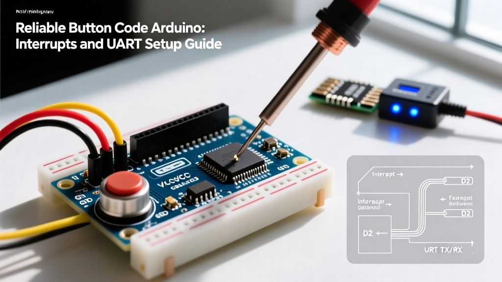
To achieve non-blocking communication, your button code Arduino architecture must utilize Hardware Interrupts. An Interrupt Service Routine (ISR) halts the main program execution the microsecond a pin changes state, ensuring no physical press is ever missed, regardless of what the UART or SPI buses are doing.
Configuring the Interrupt Service Routine (ISR)
According to the Arduino attachInterrupt() Reference, you must map the physical pin to an interrupt vector. On an Arduino Uno R4 Minima or STM32F103C8T6, pins 2 and 3 are standard external interrupts.
Crucially, any variable modified inside the ISR and read in the main loop must be declared with the volatile keyword. This prevents the compiler from caching the variable in a CPU register, which would cause the main loop to read stale data.
volatile bool buttonTriggered = false;
volatile unsigned long lastInterruptTime = 0;
const int BUTTON_PIN = 2;

void setup() {
  pinMode(BUTTON_PIN, INPUT_PULLUP);
  Serial.begin(115200);
  // Attach interrupt on FALLING edge (pin goes from HIGH to LOW when pressed)
  attachInterrupt(digitalPinToInterrupt(BUTTON_PIN), handleButtonPress, FALLING);
}

void handleButtonPress() {
  // Basic software debouncing inside ISR using micros()
  unsigned long currentTime = micros();
  if (currentTime - lastInterruptTime > 5000) { // 5ms debounce window
    buttonTriggered = true;
    lastInterruptTime = currentTime;
  }
}

void loop() {
  if (buttonTriggered) {
    buttonTriggered = false; // Reset flag immediately
    transmitUARTPacket();    // Handle communication outside the ISR
  }
}
Expert Rule: Never usedelay(),Serial.print(), or complex math inside an ISR. The ISR should only set flags and record timestamps. Heavy lifting, like UART packet framing, belongs in the mainloop().
Hardware Debouncing: The Schmitt Trigger Approach
While software debouncing using micros() is common, it consumes CPU cycles and can still fail under severe Electromagnetic Interference (EMI). For industrial communication nodes, hardware debouncing is mandatory. As detailed in the SparkFun Switch Basics Tutorial, an RC low-pass filter combined with a Schmitt trigger provides bulletproof signal conditioning.
- RC Filter: Place a 10kΩ pull-up resistor and a 100nF ceramic capacitor to ground at the switch junction. This creates a time constant ($\tau = R \times C$) of 1ms, physically smoothing out the high-frequency bounce.
- Schmitt Trigger: Route the filtered signal through a 74HC14 hex inverter. The Schmitt trigger introduces hysteresis, ensuring the output snaps cleanly from HIGH to LOW without oscillating during the capacitor's charge/discharge curve.
UART Communication Setup: Transmitting Button States
Once the button press is cleanly registered, the MCU must communicate this event to a host system (like a Raspberry Pi 5 or a centralized PLC). Sending raw ASCII strings like "Button 1 Pressed" is inefficient and prone to parsing errors. Instead, use binary packet framing.
Binary Packet Structure
A robust UART packet for a button event should include a Start Byte, Node ID, State, Timestamp, and a CRC8 checksum to guarantee data integrity over long RS-485 or TTL serial lines.
| Byte Position | Field Name | Size | Description |
|---|---|---|---|
| 0 | STX (Start) | 1 Byte | Fixed 0x02 to signal packet start |
| 1 | Node ID | 1 Byte | Unique identifier for the specific Arduino node (e.g., 0x1A) |
| 2 | Event State | 1 Byte | 0x01 for Press, 0x00 for Release |
| 3-6 | Timestamp | 4 Bytes | 32-bit millis() value (Big-Endian) |
| 7 | CRC8 | 1 Byte | Cyclic Redundancy Check of bytes 1 through 6 |
| 8 | ETX (End) | 1 Byte | Fixed 0x03 to signal packet end |
By structuring your button code Arduino output this way, the receiving host can easily synchronize with the byte stream, verify the CRC8 checksum, and discard corrupted packets caused by UART line noise.
Advanced Edge Cases: EMI and Ghosting in Industrial Environments
When deploying MCU nodes near heavy machinery, relays, or variable frequency drives (VFDs), long wires connecting buttons to the Arduino act as antennas. They pick up EMI, inducing voltage spikes that the MCU interprets as valid button presses. This phenomenon, known as ghosting, will destroy the reliability of your communication network.
Solving EMI with Optocouplers
To completely isolate the button circuitry from the sensitive MCU logic, insert a PC817 optocoupler ($0.10 per unit) between the switch and the Arduino pin. The button drives an internal infrared LED, which triggers a phototransistor on the MCU side. Because there is no physical electrical connection between the switch wiring and the Arduino ground plane, ground loops and high-voltage EMI spikes are physically blocked from reaching the microcontroller.
Troubleshooting Common Failure Modes
Even with perfect code, physical layer issues can disrupt communication. Use this diagnostic matrix when your button code Arduino setup misbehaves:
- Double Triggers on Release: You are likely triggering on the
CHANGEinterrupt mode instead ofFALLING. Switch toFALLINGto only capture the initial press, or implement a state-machine in the ISR to track both press and release edges independently. - Missed Presses During UART Transmission: If your main loop is using
Serial.print()without checking the TX buffer, the CPU might block. Ensure you are using non-blocking serial libraries or hardware UART buffers (available natively on the Arduino Mega 2560 and ESP32). - Random Ghost Presses: Your internal pull-up resistor (typically 30kΩ - 50kΩ on AVR chips) is too weak for a noisy environment. Disable
INPUT_PULLUPand solder an external 4.7kΩ or 10kΩ pull-up resistor to the 3.3V/5V rail to stiffen the logic line. - UART Packet Desynchronization: If the host misses a byte, the entire packet alignment shifts. Always implement a timeout on the host receiver. If the ETX (
0x03) byte is not received within 10ms of the STX byte, flush the serial buffer and wait for the next STX marker.
By combining hardware-level signal conditioning, non-blocking interrupt architecture, and structured UART packet framing, your button code Arduino projects will achieve the industrial-grade reliability required for modern communication networks.