
The Anatomy of an I2C Bus: Why Scanners Are Mandatory
When wiring up a new SSD1306 OLED display, a BME280 environmental sensor, or a PCA9685 PWM driver, the most common point of failure isn't your code—it is the physical I2C bus. The Inter-Integrated Circuit (I2C) protocol relies on a multi-master, multi-slave architecture using just two wires: SDA (data) and SCL (clock). However, because I2C uses an open-drain (or open-collector) wired-AND configuration, the bus requires external pull-up resistors to function. If your pull-ups are missing, incorrectly sized, or if a logic-level mismatch exists, your microcontroller will simply see a dead bus.
This is where an Arduino I2C scanner becomes your most critical diagnostic tool. Before writing a single line of device-specific library code, running a raw bus scanner sketch verifies that the master can physically detect the slave's hexadecimal address. In this guide, we will build a robust scanner, decode the results, and dive deep into advanced protocol troubleshooting for modern 2026 development boards like the Arduino Uno R4 Minima and ESP32-S3.
The Ultimate Arduino I2C Scanner Sketch
The standard scanner iterates through all 127 possible 7-bit I2C addresses, initiating a transmission and listening for an ACKnowledge (ACK) bit from a slave. Below is an optimized version of the classic scanner, updated with Fast Mode (400 kHz) support and proper serial formatting.
#include <Wire.h>

void setup() {
  Serial.begin(115200);
  while (!Serial); // Wait for serial monitor (crucial for Uno R4 / ESP32)

  Wire.begin();
  // Wire.setClock(400000); // Uncomment to test Fast Mode (400kHz)

  Serial.println("\n--- ElectricalFlux I2C Bus Scanner ---");
}

void loop() {
  byte error, address;
  int nDevices = 0;

  for (address = 1; address < 127; address++ ) {
    Wire.beginTransmission(address);
    error = Wire.endTransmission();

    if (error == 0) {
      Serial.print("Device found at 0x");
      if (address < 16) Serial.print("0");
      Serial.println(address, HEX);
      nDevices++;
    } else if (error == 4) {
      Serial.print("Unknown error at address 0x");
      if (address < 16) Serial.print("0");
      Serial.println(address, HEX);
    }
  }

  if (nDevices == 0) {
    Serial.println("No I2C devices found. Check wiring and pull-ups.\n");
  } else {
    Serial.println("Scan complete.\n");
  }
  delay(5000); // Wait 5 seconds before next scan
}
According to the Arduino Wire Library Reference, Wire.endTransmission() returns 0 on success, but returns 4 if there is an unknown error (often indicative of a bus lockup or severe noise). Always monitor this return value in production environments.
Decoding the Output: Common Sensor and Display Addresses
When your scanner outputs a hex value, you need to map it to your hardware. Many manufacturers hardcode addresses, while others provide jumper pads or address-select pins (like A0, A1) to shift the base address. Below is a reference matrix of the most common I2C components used in modern DIY electronics.
| Component / IC | Common Hex Addresses | Address Selection Method |
|---|---|---|
| SSD1306 (OLED Display) | 0x3C, 0x3D | Hardware resistor pad on PCB |
| PCF8574 (LCD Backpack) | 0x27, 0x3F | A0, A1, A2 jumper pads |
| BME280 / BMP280 | 0x76, 0x77 | SDO pin (High = 0x77, Low = 0x76) |
| MPU6050 (IMU) | 0x68, 0x69 | AD0 pin (High = 0x69, Low = 0x68) |
| PCA9685 (PWM Driver) | 0x40 - 0x7F | A0-A5 address pins |
| VL53L0X (ToF Sensor) | 0x29 (Default) | Software configurable via I2C |
Advanced Protocol Troubleshooting: When the Scanner Fails
If your Arduino I2C scanner returns 'No devices found' or hangs indefinitely, do not immediately assume your sensor is dead. I2C is notoriously fragile at the physical layer. Here are the expert-level failure modes and how to resolve them.
1. The 'Stuck SDA' Bus Lockup
If a master microcontroller resets or loses power mid-transaction, the slave device may be left waiting to transmit a data bit. If that bit happens to be a '0', the slave will hold the SDA line LOW indefinitely. Because I2C uses wired-AND logic, a single device holding SDA low prevents any new START conditions, effectively bricking the bus.
Expert Fix: To recover a locked bus without power-cycling the slave, reconfigure the master's SCL pin as a standard GPIO output. Manually toggle the SCL pin HIGH and LOW 9 times. This forces the slave to clock out its remaining bits and release the SDA line. Afterward, send a STOP condition and reinitialize the Wire library.
2. Logic Level Mismatches (3.3V vs 5V)
Mixing 5V boards (like the classic Uno or Mega) with 3.3V sensors (like the BME688 or modern ESP32-S3 setups) is a recipe for silent failures or fried silicon. The I2C specification defines a HIGH signal as roughly 70% of VCC. A 3.3V sensor outputting 3.3V might not register as a logic HIGH on a 5V Arduino (which expects ~3.5V). Conversely, feeding 5V into a 3.3V sensor's SDA pin will destroy its internal protection diodes.
The 2026 Solution: Use a bi-directional logic level shifter. The BSS138 MOSFET-based shifter (typically $1.50 for a 4-channel breakout) is the budget standard. For high-speed or mission-critical industrial applications, use an active I2C level translator IC like the PCA9306 (~$2.10), which includes dedicated edge-rate acceleration for cleaner signal transitions.
3. Bus Capacitance and Pull-Up Resistor Sizing
The NXP UM10204 I2C Specification strictly limits total bus capacitance to 400 pF. Every wire, breadboard track, and sensor module adds parasitic capacitance (typically 15-50 pF per module). If capacitance is too high, the voltage rise time on the SDA/SCL lines becomes too slow, causing data corruption at higher speeds.
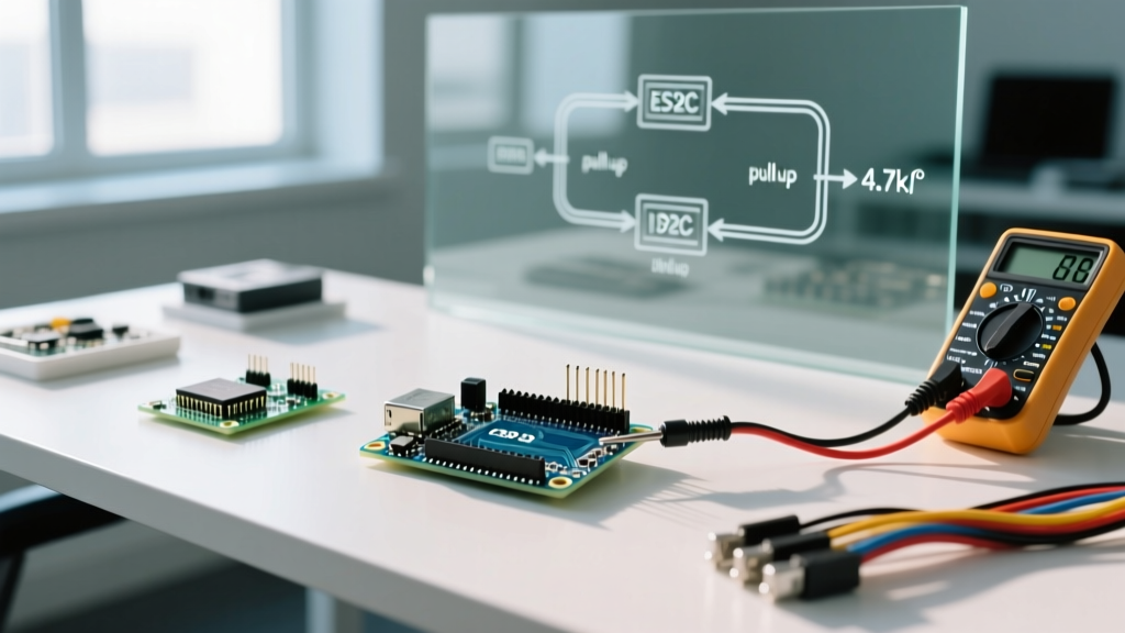
- Standard Mode (100 kHz): Use 4.7kΩ pull-up resistors to 5V (or 3.3V). This provides a safe balance between rise time and current sinking (approx 1mA).
- Fast Mode (400 kHz): Drop to 2.2kΩ or even 1kΩ pull-ups to charge the parasitic capacitance faster and meet the strict 300ns rise-time requirement.
- Long Wire Runs: If your wires exceed 30cm, abandon passive pull-ups. Use an active I2C bus buffer like the PCA9600, which splits the bus into local and main segments, isolating capacitance.
4. Clock Stretching Quirks on the ESP32-S3
Some sensors, notably the SHT31 temperature/humidity sensor, use 'clock stretching'—holding the SCL line LOW to force the master to wait while the sensor processes data. Early ESP32 hardware I2C peripherals had notorious bugs handling clock stretching, leading to bus timeouts. While the ESP32-S3 silicon has largely resolved this, the Arduino core implementation can still be finicky.
If your scanner hangs on an ESP32 when a clock-stretching device is attached, increase the Wire timeout before calling Wire.begin():
Wire.setTimeOut(100); // Set timeout to 100 millisecondsFor a deeper dive into protocol physics and edge cases, the SparkFun I2C Protocol Guide provides excellent oscilloscope captures of what these failures look like at the signal level.
Hardware Tools to Pair with Your Scanner
While the Arduino I2C scanner sketch is free, pairing it with the right hardware accelerates debugging:
- I2C Multiplexer (PCA9548A): If you need to connect multiple sensors with the same hardcoded address (e.g., five VL53L0X ToF sensors all at 0x29), this $4.50 chip creates 8 virtual I2C buses, allowing the scanner to map them sequentially.
- Digital Oscilloscope / Logic Analyzer: A $15 USB logic analyzer (like the Saleae Logic clone) running PulseView software will decode the I2C hex packets in real-time, proving whether the master is actually sending the correct address bits.
- Multimeter: Always measure the voltage on the SDA and SCL lines at idle. If they do not read exactly VCC (e.g., 3.28V or 4.95V), your pull-up resistors are missing or the bus is stuck LOW.
Conclusion
An Arduino I2C scanner is not just a beginner's first sketch; it is a fundamental protocol diagnostic tool. By understanding the underlying physics of open-drain buses, respecting capacitance limits, and utilizing proper logic-level translation, you can eliminate 95% of all communication errors before you even begin writing your application logic. Keep this scanner in your default firmware arsenal, and never wire a new I2C peripheral without verifying its address first.