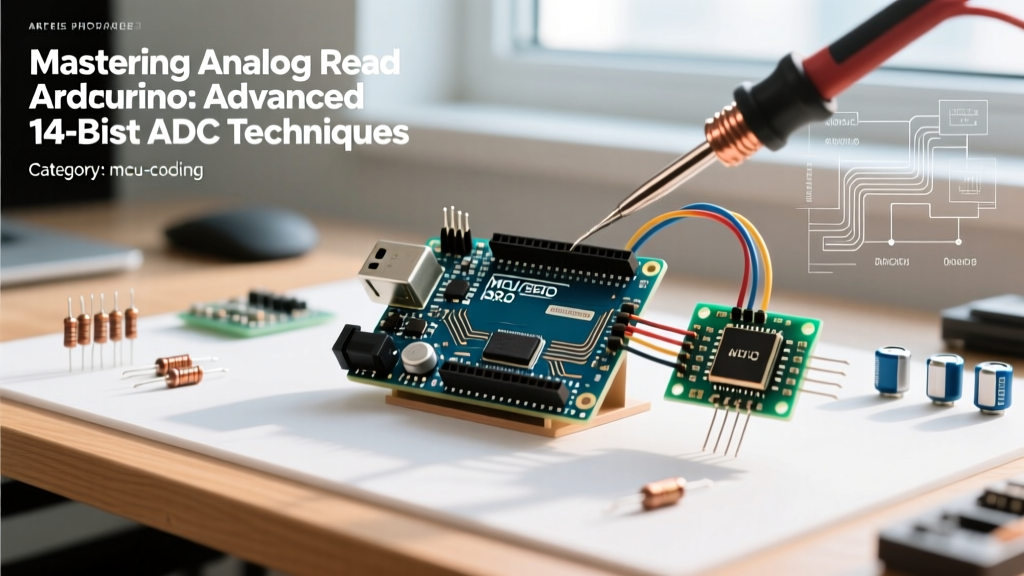

The Hardware Reality: Moving Beyond the 10-Bit Era
For over a decade, the standard analogRead() function returned a 10-bit integer (0-1023), mapping a 0-5V range to roughly 4.88mV per step. While sufficient for basic potentiometer inputs or crude light sensing, this resolution is entirely inadequate for modern precision applications like load cell amplification, RTD temperature sensing, or high-fidelity audio envelope tracking. If you are looking to optimize your analog read arduino implementation for professional-grade data acquisition, you must look at the hardware evolution of the ecosystem.
As of 2026, the ecosystem has shifted heavily toward 32-bit ARM Cortex-M architectures. The Arduino Uno R4 Minima, powered by the Renesas RA4M1, features a native 14-bit ADC. Meanwhile, the flagship Arduino Portenta H7 (STM32H747) boasts 16-bit ADCs capable of 3.6 MSPS (Mega Samples Per Second). However, simply calling analogReadResolution(14) does not magically yield precision. The silicon is only as good as the analog front-end (AFE) and the software sampling strategies you deploy.
Board Comparison: ADC Capabilities in 2026
| Board Model | MCU Core | ADC Resolution | Max Sample Rate | Typical Price (USD) |
|---|---|---|---|---|
| Uno R3 (Legacy) | ATmega328P | 10-bit | 15 kSPS | $27.00 |
| Uno R4 Minima | Renesas RA4M1 | 14-bit | 500 kSPS | $29.50 |
| Portenta H7 | STM32H747 | 16-bit | 3.6 MSPS | $108.00 |
| Teensy 4.1 | NXP i.MX RT1062 | 12-bit (Dual) | 1 MSPS | $39.95 |
Advanced Technique 1: Hardware Oversampling and Decimation
According to Analog Devices' foundational Nyquist tutorials, you can artificially increase the resolution of an ADC by oversampling and decimating. The mathematical rule is that for every additional bit of resolution ($n$), you must oversample by a factor of $4^n$. To extract 16 bits of resolution from the Uno R4's 14-bit ADC, you need $4^2 = 16$ samples.
However, simply summing 16 samples in a for loop is not enough. The ADC requires a small amount of inherent noise (dither) to toggle the least significant bits (LSBs). If your signal is too clean, oversampling will just return the exact same 14-bit value 16 times. You must ensure at least 1 LSB of wideband noise is present at the input.
Optimized Oversampling Code Block
// Configure Uno R4 for 14-bit resolution
void setup() {
  analogReadResolution(14);
  Serial.begin(115200);
}

uint16_t read16BitOversampled(uint8_t pin) {
  uint32_t accumulator = 0;
  // 16x oversampling to gain 2 extra bits (14 -> 16)
  for (int i = 0; i < 16; i++) {
    accumulator += analogRead(pin);
    // Micro-delay to allow S/H cap to settle and capture noise dither
    delayMicroseconds(5);
  }
  // Decimate: shift right by 2 bits (divide by 4) to scale back to 16-bit range
  return (uint16_t)(accumulator >> 2);
}

void loop() {
  uint16_t precisionVal = read16BitOversampled(A0);
  Serial.println(precisionVal); // Output range: 0 - 65535
  delay(100);
}
Advanced Technique 2: Defeating Source Impedance Limits
The most common failure mode in precision analog read Arduino projects is ignoring the source impedance. Inside the MCU, the ADC uses a Sample-and-Hold (S/H) circuit featuring a tiny internal capacitor (typically 5pF to 15pF). When the multiplexer switches to your pin, this capacitor must charge to the input voltage within a fraction of an ADC clock cycle.
If your sensor has a high output impedance (e.g., a 100kΩ voltage divider for battery monitoring), the internal capacitor will not charge fully before the conversion begins. The result? Non-linear readings that drift based on the previous channel read.
The RC Filter Solution
Never connect a high-impedance source directly to an ADC pin. Instead, design a passive RC low-pass filter. This serves two purposes: it limits high-frequency EMI, and the external capacitor acts as a 'charge reservoir' to instantly fill the internal S/H capacitor.
- Resistor: 100Ω to 470Ω (Metal film, 1% tolerance)
- Capacitor: 100nF to 1µF (Crucial: Use C0G/NP0 dielectric ceramic capacitors. X7R or Y5V capacitors exhibit piezoelectric effects and voltage coefficients that will introduce massive non-linear distortion into your ADC readings).
- Cutoff Frequency: With 100Ω and 100nF, $f_c = 1 / (2 \pi R C) \approx 15.9$ kHz, which effectively eliminates switching noise from nearby DC-DC converters.
Advanced Technique 3: Voltage Reference (VREF) Stabilization
Expert Insight: Your ADC is essentially a ratiometric voltmeter. It doesn't measure absolute voltage; it measures the ratio of the input voltage to the VREF pin. If your VREF is noisy, your data is noisy, regardless of how many bits your ADC has.
Powering an Arduino via USB introduces 50mV to 150mV of high-frequency switching noise from the host PC's power supply. If you use the default DEFAULT reference (tied to VCC), this noise is injected directly into your ADC calculations.
The Fix: Bypass the internal regulator and feed the AREF pin with a dedicated, low-noise shunt or series voltage reference. The LM4040AIZ-4.096 (approximately $2.15 at major distributors) is a precision shunt reference with a typical noise voltage of 20µV RMS. By biasing it with a 1kΩ resistor from the 5V rail and feeding the AREF pin, you establish a rock-solid 4.096V baseline. This also makes the math trivial: 4.096V / 65536 (16-bit) = exactly 0.0625mV per LSB.
Software Digital Filtering: IIR vs. FIR
When continuous high-speed sampling is required, hardware oversampling might consume too much CPU time. In these cases, implementing an Infinite Impulse Response (IIR) Exponential Moving Average (EMA) filter in software provides excellent noise rejection with minimal computational overhead.
float alpha = 0.05; // Smoothing factor (lower = more smoothing, slower response)
float filteredValue = 0;

void loop() {
  float raw = analogRead(A0);
  filteredValue = (alpha * raw) + ((1.0 - alpha) * filteredValue);
  // Use filteredValue for PID control loops or telemetry
}
For applications requiring strict phase-linearity (like audio waveform analysis), avoid IIR filters and instead implement a Finite Impulse Response (FIR) moving average or use a hardware DMA (Direct Memory Access) pipeline to offload the buffering from the main CPU core.
Troubleshooting Common Analog Edge Cases
- Floating Pin Erratic Jumps: If an unconnected analog pin reads random values between 0 and 1023 (or 16383), this is normal. The high-impedance CMOS gate is acting as an antenna for ambient 50/60Hz mains hum. Always tie unused analog pins to GND via a 10kΩ resistor in production PCBs.
- PWM Cross-Talk: Running
analogWrite()on a pin adjacent to your ADC input on the physical silicon die can cause capacitive coupling inside the MCU package. If you notice a 490Hz or 980Hz ripple in your ADC data, move your sensitive analog trace to a pin physically separated from the PWM outputs on the schematic. - Ground Loop Offsets: When measuring a remote sensor powered by a separate supply, the ground potential between the sensor and the Arduino may differ by tens of millivolts due to current flowing through the ground wire. For precision differential measurements, abandon single-ended
analogRead()and use an external instrumentation amplifier (like the INA828) to reject the common-mode ground offset before the signal reaches the MCU.
Conclusion
Mastering the analog read Arduino function is less about the C++ syntax and entirely about mastering the physics of the analog domain. By upgrading to 14-bit or 16-bit hardware, implementing mathematical oversampling, stabilizing your VREF with precision shunt references, and respecting source impedance limits, you transform a basic microcontroller into a laboratory-grade data acquisition system.