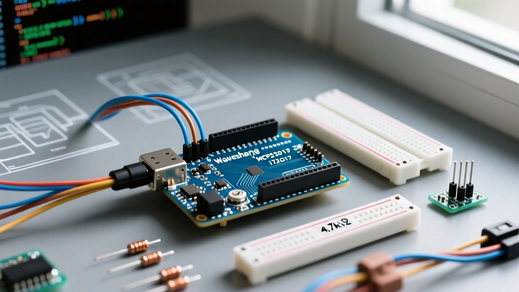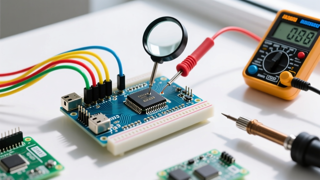

Why Your Arduino Needs a Bootloader Recovery
Whether you are deploying standalone ATmega328P microcontrollers to save costs or recovering a bricked board after a failed sketch upload, understanding how to perform an Arduino upload bootloader operation via In-System Programming (ISP) is an essential skill. In 2026, bare ATmega328P-PU chips cost roughly $2.80, compared to $26.00 for a fully assembled Uno R3. However, bare chips from the factory lack the Optiboot bootloader required for standard USB serial programming.
Furthermore, incorrect fuse bit configurations or interrupted uploads can corrupt the bootloader on an existing board, rendering the main microcontroller unresponsive to the Arduino IDE. This tutorial provides a deep-dive walkthrough on burning the bootloader, configuring AVR fuse bits, and troubleshooting complex edge cases using a dedicated ISP programmer.
Hardware Bill of Materials (2026 Pricing)
To execute this recovery or standalone setup, you will need a reliable ISP programmer and the target hardware. While you can use a second Arduino as an ISP, a dedicated hardware programmer is vastly superior for handling clock-speed mismatches and providing stable 3.3V/5V power switching.
- USBasp V2.0 Programmer: ~$4.50. Ensure you buy a version with the 10-pin to 6-pin adapter and the jumper for slow SCK (Serial Clock) speeds.
- ATmega328P-PU Microcontroller: ~$2.80 (DIP-28 package).
- 16MHz HC49/S Quartz Crystal: ~$0.50.
- 2x 22pF Ceramic Capacitors: ~$0.10 (Required for the crystal oscillator load).
- 10kΩ Pull-up Resistor: ~$0.05 (Critical for the RESET pin).
- Breadboard and Jumper Wires: Standard prototyping gear.
ICSP Wiring Matrix: USBasp to ATmega328P-PU
The In-Circuit Serial Programming (ICSP) header relies on the SPI protocol. Incorrect wiring here will not damage the chip, but it will result in immediate avrdude synchronization failures. Below is the exact pin mapping for a standalone DIP-28 ATmega328P.
| USBasp 6-Pin Header | ATmega328P-PU Pin Name | DIP-28 Pin Number | Notes & Requirements |
|---|---|---|---|
| MISO | PB4 (MISO) | 18 | Master In, Slave Out |
| VCC | VCC | 7 | Also connect to Pin 20 (AVCC) |
| SCK | PB5 (SCK) | 19 | Serial Clock |
| MOSI | PB3 (MOSI) | 17 | Master Out, Slave In |
| GND | GND | 8 | Also connect to Pin 22 (GND) |
| RESET | PC6 (RESET) | 1 | Requires 10kΩ pull-up to VCC |
Critical Hardware Note: The 10kΩ pull-up resistor on the RESET pin (Pin 1) is mandatory. Without it, the RESET line floats, causing the microcontroller to spontaneously reset during the multi-second bootloader flash sequence, resulting in a corrupted flash memory state.
Step-by-Step Walkthrough: Arduino Upload Bootloader
Phase 1: IDE and Programmer Setup
Open the Arduino IDE (version 2.3.x or newer). Navigate to Tools > Board and select Arduino Uno. This selection tells the IDE to expect an ATmega328P running at 16MHz with the Optiboot bootloader.
Next, navigate to Tools > Programmer and select USBasp. If you are using a clone USBasp that throws an rc=-1 error, you may need to install the Zadig driver on Windows to replace the default libusb driver with WinUSB.
Phase 2: Burning the Bootloader and Setting Fuses
With the hardware connected and the IDE configured, click Tools > Burn Bootloader. This single action triggers a complex sequence under the hood via the avrdude command-line utility:
- Chip Erase: The entire flash memory is wiped, including any corrupted sketches.
- Fuse Programming: The Low, High, and Extended fuse bytes are written to configure the clock source and bootloader size.
- Flash Programming: The Optiboot hex file is written to the highest memory addresses.
- Lock Bits: The bootloader section is locked to prevent accidental overwriting by user sketches.
Watch the console output at the bottom of the IDE. A successful operation will conclude with avrdude done. Thank you. If it fails, proceed to the troubleshooting section.
Deep Dive: AVR Fuse Bits Explained
When you initiate the Arduino upload bootloader process, the IDE writes specific hexadecimal values to the AVR fuse bits. According to the AVR Fuse Calculator, the standard Arduino Uno profile requires the following settings:
- Low Fuse (0xFF): Configures the clock source. 0xFF sets the CKSEL bits to use an external full-swing crystal oscillator (16MHz) with a startup time of 16K CK + 65ms.
- High Fuse (0xDE): Enables the BOOTRST (Boot Reset) vector and sets the bootloader section size to 256 words (512 bytes). This ensures the chip jumps to the Optiboot bootloader on power-up before falling back to the user sketch.
- Extended Fuse (0xFD): Configures the Brown-out Detection (BOD) level to 2.7V. This prevents the microcontroller from executing garbage code if the power supply dips during operation.
Modifying these fuses incorrectly is the primary cause of bricked chips. For instance, setting the Low Fuse to 0xE2 switches the chip to the internal 8MHz RC oscillator, which will cause standard 115200-baud serial uploads to fail due to clock drift.
Advanced Troubleshooting & Edge Cases
Even with perfect wiring, the avrdude backend can throw cryptic errors. Refer to the AVRDUDE Documentation for deep protocol specifics, but here are the most common field failures and their exact solutions.
Failure 1: avrdude: error: program enable: target doesn't answer
The Cause: The programmer cannot establish an SPI handshake. This almost always means the microcontroller's clock is not running. If you are working with a bare chip that previously had its fuses set to an external crystal, but you forgot to plug the 16MHz crystal into the breadboard, the chip is effectively deaf.
The Fix: Connect the 16MHz crystal and 22pF capacitors to pins 9 and 10 (XTAL1 and XTAL2). If the chip is severely bricked and you don't have a crystal, you can inject an 8MHz square wave directly into XTAL1 (Pin 9) using a function generator or the PWM output of a secondary Arduino. Once the external clock is provided, re-run the bootloader burn process to reset the fuses.
Failure 2: USBasp rc=-1 or SCK Speed Mismatch
The Cause: A fresh ATmega328P from the factory runs on its internal 1MHz RC oscillator. The SPI protocol requires the programmer's SCK (Serial Clock) to be at least 4 times slower than the target's CPU clock. Many modern USBasp programmers default to a 1.5MHz SCK, which is too fast for a 1MHz target, causing data corruption during the handshake.
The Fix: If your USBasp has a physical jumper labeled 'Slow SCK', bridge it to drop the programmer speed to 8kHz. Alternatively, if you are using the command line, append the -B 125 flag to your avrdude command to manually set the bitclock to 125 microseconds, ensuring a safe handshake with the 1MHz target.
Failure 3: Verification Error on Lock Bits
The Cause: The bootloader flashed successfully, but the final lock-bit verification failed. This often happens with cheap clone USBasps that have outdated firmware lacking support for the specific lock-bit memory space of the ATmega328P.
The Fix: The chip is actually programmed and will function perfectly. You can safely ignore this specific error. To permanently fix it, you must update the USBasp's firmware using a secondary ISP programmer, flashing the official Arduino Official ISP Guide recommended firmware or the latest Thomas Fischl USBasp release.
Conclusion
Mastering the Arduino upload bootloader process transforms you from a simple sketch-uploader into a true embedded systems engineer. By understanding the physical SPI wiring, the implications of AVR fuse bits, and the timing constraints of the avrdude protocol, you can recover virtually any bricked ATmega board and confidently design standalone microcontroller circuits for your 2026 IoT and robotics projects.