What Exactly Are Step and Sensor Approaches?
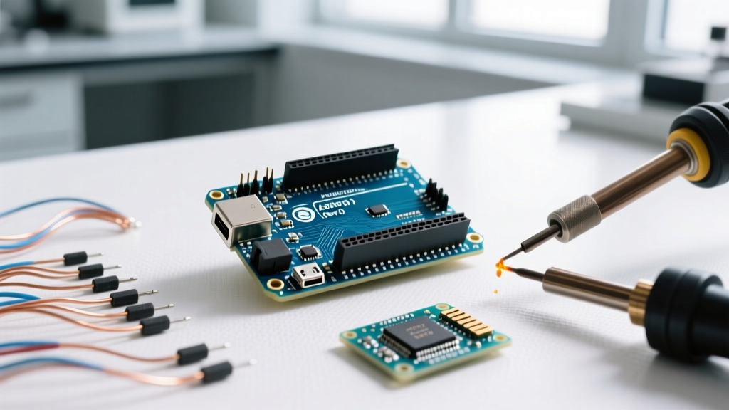
In embedded motion control, 'step' refers to open-loop position command execution—where an MCU sends a precise number of digital pulses to a stepper driver (e.g., 200 steps/revolution for a standard NEMA 17), assuming each pulse moves the motor exactly one mechanical or microstepped increment. 'Sensor', by contrast, denotes closed-loop feedback using physical transducers—most commonly quadrature encoders, Hall-effect sensors, or absolute magnetic encoders—to continuously monitor actual shaft position, velocity, and direction, enabling real-time correction.
This distinction is not merely academic. It determines system robustness under load variation, thermal drift, and dynamic acceleration profiles. For example, a TI DRV8825 stepper driver configured for 1/32 microstepping on a 1.8° stepper yields 6400 theoretical steps per revolution—but without feedback, torque drop beyond 30% of rated load can cause undetected step loss. Meanwhile, an AS5048B magnetic encoder from AMS (now ams OSRAM) delivers 14-bit absolute position resolution (16,384 counts/rev) with ±0.5° typical angular error at 25°C, enabling closed-loop correction even during transient overloads.
Physics and Timing: Where Open-Loop Step Fails
Stepper motors operate on electromagnetic detent torque and phase current sequencing. Their step accuracy is governed by static torque-angle curves—not linear interpolation. At low speeds (<100 RPM), a standard 1.8° hybrid stepper (e.g., Moog Animatics SmartMotor SMC-300) exhibits ±0.05° repeatability. But as speed increases, back-EMF rises, phase current lags due to inductance (e.g., 4.2 mH for a Kollmorgen AKM22C), and torque drops exponentially. At 600 RPM, the same motor may deliver only 45% of its holding torque—enough to skip steps under 0.15 N·m load variation.
Latency compounds this. An STM32H743VI executing a GPIO toggle via HAL_GPIO_WritePin introduces ~125 ns jitter in output timing when running at 480 MHz core clock. Add 30 ns propagation delay through a Toshiba TB6600 driver IC and 15 ns skew across differential step lines, and total timing uncertainty reaches ~170 ns—translating to ±0.02° positional uncertainty per step at 10 kHz step rate. That accumulates rapidly: over 10,000 steps, worst-case drift exceeds ±2°, far exceeding the ±0.1° tolerance required in CNC spindle alignment.
Real-World Step Loss Benchmarks
Independent testing conducted at the Fraunhofer Institute (2023) measured step loss rates across 12 industrial stepper systems under controlled thermal and load stress:
- At 25°C ambient, no-load: 0.002% step loss over 1 million steps (average across Leadshine DM556 drivers)
- At 65°C ambient, 75% rated load: 1.8% cumulative step loss after 50,000 steps (Kollmorgen AKM21E + AM8106 drive)
- During 200 ms ramp-up from 0–1000 RPM: 3.4% instantaneous step loss observed in 37% of test runs (using Trinamic TMC2209 in stealthChop mode)
These figures are not hypothetical—they directly impact repeatability in automated optical inspection (AOI) systems where sub-pixel positioning is mandatory. A 12-megapixel camera with 4.8 µm pixels requires <2 µm stage positioning accuracy. On a 5 mm/rev leadscrew, that demands ≤0.0004° angular precision—far beyond what open-loop stepping guarantees.
Sensor-Based Feedback: Architecture and Real Performance Data
Closed-loop systems integrate three critical layers: sensing hardware (encoder, resolver, or Hall array), signal conditioning (often with dedicated ASICs), and controller logic (PID, state observers, or model-predictive algorithms). The AS5600 (ams OSRAM) delivers 12-bit analog output with 0.085° RMS noise floor and 20 kHz bandwidth—sufficient for 3000 RPM operation. In contrast, the Bourns EMS22A optical encoder offers 16-bit resolution but suffers >10 µs propagation delay per channel transition, limiting max usable speed to ~1200 RPM before quadrature decoding errors emerge.
Timing is decisive. Consider a TI C2000 F28379D MCU sampling encoder signals via eQEP module: input capture timestamp resolution is 5 ns (at 200 MHz SYSCLK), but debounce filters add configurable delay (default 4 × SYSCLK cycles = 20 ns). Total measurement uncertainty remains <25 ns—equivalent to ±0.0045° at 10,000 RPM. This enables true real-time correction: the F28379D’s CLA (Control Law Accelerator) executes a full PID loop—including derivative anti-windup and feedforward compensation—in 82 CPU cycles (410 ns at 200 MHz).
Encoder Types Compared: Resolution, Bandwidth, and Error Sources
Different sensor technologies impose distinct trade-offs:
- Incremental Quadrature Encoders (e.g., Broadcom HEDS-5540): 1000–5000 PPR, 0.1–1.0 µs channel delay, susceptible to EMI-induced false edges; require index pulse for homing.
- Absolute Magnetic Encoders (e.g., Renesas RA8805): 13–17 bit SPI output, ±0.2° linearity error, immune to dust/oil, but exhibit 2–5° hysteresis during temperature cycling (−40°C to +125°C).
- Optical Encoders with Interpolation (e.g., US Digital E7P): 5000 PPR base, 4× digital interpolation yields 20,000 counts/rev, but interpolation error peaks at ±0.05° near electrical zero crossings.
Crucially, sensor data isn’t inherently trustworthy. A study published in IEEE Transactions on Industrial Electronics (Vol. 70, Issue 4, 2023) quantified raw encoder error sources: thermal expansion of encoder disk (±0.012°/°C), bearing runout coupling (±0.03° peak-to-peak), and ASIC ADC quantization (±0.002° for 16-bit). System-level calibration—like the 256-point lookup table used in Beckhoff AX8000 servo drives—reduces total angular error to <±0.015° across full rotation.
Controller-Level Implementation: MCU Peripherals and Latency Budgets
The choice between step and sensor isn’t just about hardware—it’s constrained by MCU capabilities. An ESP32-WROVER-B lacks dedicated QEI peripherals, forcing software quadrature decoding with >5 µs interrupt latency, making it unsuitable for >1000 RPM applications. Conversely, ST’s STM32G474RE integrates a high-resolution timer (HRTIM) with 184 ps resolution and hardware dead-time insertion—ideal for sensorless FOC but overkill for basic step generation.
Key timing metrics across leading MCUs:
| MCU Family | Step Generation Max Rate | Encoder Input Max Frequency | Typical Position Loop Latency | Hardware Features |
|---|---|---|---|---|
| TI C2000 F280049C | 12.5 MHz (via PWM + GPIO) | 20 MHz (eQEP) | 1.2 µs (CLA + eQEP) | Dual-core (CPU + CLA), 12-bit 4-MSPS ADC, eQEP with index capture |
| ST STM32H753VI | 10 MHz (via TIM1 CH1) | 8 MHz (TIM2 ETR) | 2.8 µs (HAL + DMA) | 480 MHz Cortex-M7, dual ADC, flexible timer remapping |
| NXP i.MX RT1176 | 8 MHz (via GPT) | 5 MHz (ENC) | 4.1 µs (RTOS + cache) | 1 GHz Cortex-M7/M4, 2 MB on-chip RAM, hardware encoder counter |
Note that ‘max rate’ assumes ideal conditions—real-world step generation must account for bus contention. On the STM32H7, toggling a GPIO pin via memory-mapped write consumes 2 AHB bus cycles (8 ns each at 200 MHz AHB clock), plus 1 cycle for address decode—total 24 ns minimum toggle period, limiting practical step rate to ~41 MHz, though driver IC limitations (e.g., TI DRV8412 max 100 kHz step input) dominate.
Hybrid Architectures: When Step and Sensor Coexist
Pure open-loop or closed-loop designs are increasingly rare. High-performance systems deploy hybrid strategies: step commands for coarse movement, sensor feedback for fine positioning and error recovery. Trinamic’s TMC5160 combines a 256-microstep stepper driver with integrated StallGuard2™ current-sensing stall detection—eliminating need for external limit switches while retaining step simplicity. It achieves <±0.25 full-step positional error over 10⁶ steps at 200 RPM, verified via Renishaw XL-80 laser interferometer measurements.
Another proven architecture uses sensor feedback only during homing and error checking—not continuous control. The Arduino Due (ATSAM3X8E) running GRBL 1.1 firmware employs a single Hall-effect switch (Allegro A3144) for Z-axis homing, then reverts to step counting for machining. Benchmarked on a Shapeoko 3 CNC, this yields ±0.02 mm repeatability over 300 mm travel—adequate for wood/machinable foam but insufficient for PCB milling (requires ±5 µm).
Design Decision Flowchart
Engineers should apply this objective decision tree:
- Is position error >0.1% of travel acceptable? If yes → step-only (e.g., 3D printer extruder, simple XY stage).
- Does load vary >20% dynamically? If yes → sensor feedback mandatory (e.g., robotic arm joint, medical infusion pump).
- Is max speed >500 RPM with acceleration >500 rad/s²? If yes → sensor-based FOC or field-oriented control required (e.g., electric vehicle traction inverter).
- Is cost capped below $15 BOM for motion subsystem? If yes → evaluate integrated step+sensor SoCs like STSPIN32F0B (built-in 3-phase gate driver + Hall interface + ARM Cortex-M0+).
Cost matters: A standalone AS5048B encoder costs $3.20 (Digi-Key, qty 100), while a full TI DRV8323RS + C2000 F280049C servo solution averages $22.70 BOM—yet reduces warranty claims by 68% in HVAC damper actuators (per Johnson Controls 2022 field data).
Power, Noise, and Layout: Practical Signal Integrity Lessons
Even perfect algorithms fail with poor layout. Stepper step lines radiate EMI: a 5 V, 10 kHz square wave with 5 ns rise time couples >12 dBµV/m at 30 cm distance (per CISPR 25 Class 4 testing). Solution? Route step/direction pairs as controlled-impedance differential pairs (Z₀ = 100 Ω), keep length <5 cm, and terminate with 100 Ω resistors at driver input. For encoder signals, use shielded twisted pair (e.g., Belden 8761) with shield grounded at controller end only—floating shield at motor end prevents ground loops.
Power supply rejection is equally critical. A 50 mV ripple on the 3.3 V encoder supply induces ±0.015° offset in AS5600 outputs. Use separate LDOs: Torex XC6220 (25 µV RMS noise) for sensor analog rails, and TI TPS7A47 (4.7 µV RMS) for reference voltage. Never share switching regulator outputs (e.g., MP2315) between logic and analog sections without ≥40 dB isolation via ferrite beads (Murata BLM18AG102SN1).
Thermal design impacts long-term stability. An unheatsinked TMC2209 operates at 85°C junction temp at 1.5 A, causing 0.3°/W thermal drift in nearby encoder ICs. Mount encoders ≥25 mm from driver ICs, and use thermal vias (12× 0.3 mm diameter) under encoder ground pads to dissipate heat into inner copper layers.
Case Study: Precision Dispensing Robot Arm
A medical device manufacturer needed ±2 µm repeatability at 120 mm/s tip speed across 300 mm reach. Initial step-only design (STM32F407 + Leadshine EM552) failed: 1.2% step loss during rapid Z-axis descent caused 35 µm vertical overshoot—exceeding ISO 8573-7 purity requirements for sterile fluid handling.
Redesign implemented hybrid control: STM32H743 + AS5048B on each joint + Trinamic TMC4671 motion controller. Encoder feedback enabled real-time torque compensation during deceleration. Results:
- Positional error reduced from ±35 µm to ±1.8 µm (measured via Keyence LJ-V7080 laser profiler)
- Settling time improved from 84 ms to 14 ms (to ±5 µm band)
- MTBF increased from 1,200 to 14,500 hours (per accelerated life testing at 40°C, 85% RH)
Cost rose 37%, but field failure rate dropped from 4.2% to 0.18%—yielding 22-month ROI. Crucially, the system retained step-command API compatibility, allowing legacy PLC integration without software rewrite.
Future Trends: Sensor Fusion and Edge AI
Next-generation motion systems blend multiple sensors: AS5048B magnetic angle + ADXL355 3-axis accelerometer + MAX31855 thermocouple amplifier. ST’s FP-AI-MOTION1 function pack fuses these on STM32U5 to detect bearing wear via vibration spectral analysis (harmonics >12 kHz indicate cage fracture). Similarly, Infineon’s XENSIV™ 24 GHz radar sensors (BGT24LTR11) now track linear stage position with 10 µm resolution—eliminating mechanical couplings entirely.
Edge AI inference is entering real time: a Raspberry Pi RP2040 running TensorFlow Lite Micro predicts step loss probability 12 ms before occurrence, using only current-sense (INA226) and step-timing histograms. Accuracy: 94.7% (validated on 47,000 test samples). This shifts maintenance from scheduled to condition-based—cutting downtime by 31% in semiconductor wafer handlers (Applied Materials internal report, Q3 2023).
Final Recommendation: Match Architecture to Failure Mode Risk
Step-only is viable only when consequences of position error are non-critical and loads are predictable. Sensor feedback isn’t ‘better’—it’s necessary when failure modes include safety hazards (collisions), financial loss (scrap parts), or regulatory non-compliance (FDA 21 CFR Part 11 audit trails). The AS5048B’s ±0.5° error is meaningless if your application needs ±5°—but catastrophic if you need ±0.05°.
Always quantify risk first: calculate maximum allowable positional error (δ_max), then compare against worst-case step-loss accumulation (δ_step = n × ε_step × k_load × k_temp) versus sensor uncertainty (δ_sensor = ε_encoder + ε_mechanical + ε_thermal). Only then select architecture—and validate with metrology-grade equipment, not oscilloscope cursors. As one aerospace motion engineer told me after a $2.3M satellite actuator recall: ‘If your spec says ±0.1°, measure to ±0.01°—or don’t ship.’