
The Exact Physical Dimensions of the Arduino Mega 2560
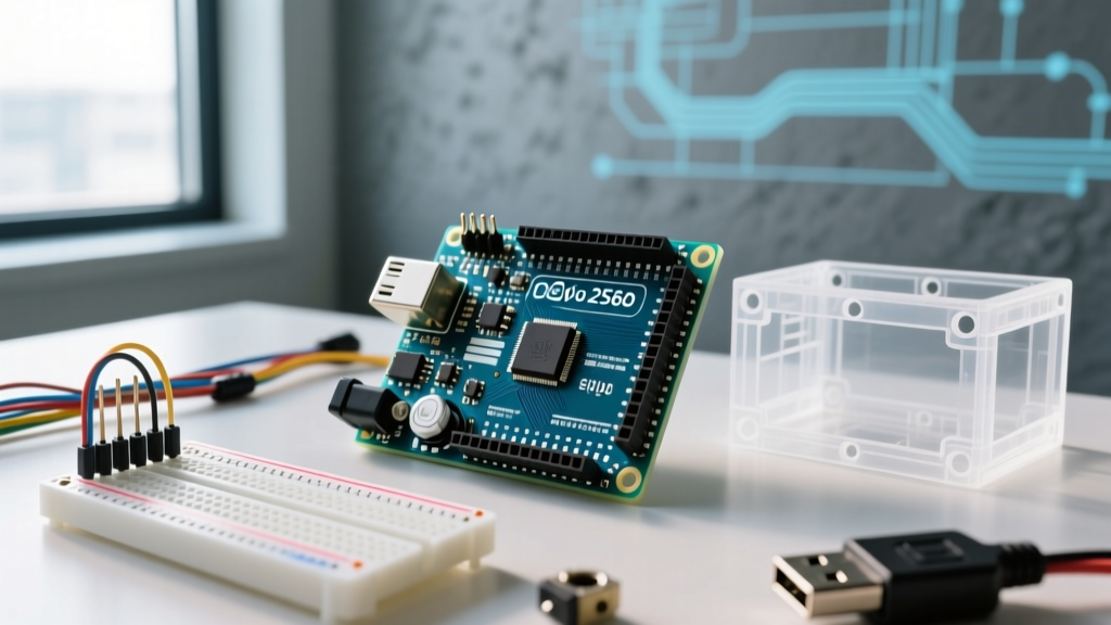
When transitioning from smaller microcontrollers to the heavyweight champion of the Arduino ecosystem, understanding the physical footprint is your first critical step. The official Arduino Mega 2560 Rev3 is designed for complex projects requiring extensive I/O, but its larger footprint introduces unique mechanical challenges for beginners.
Here are the precise, factory-spec measurements for the bare PCB:
- Length: 101.52 mm (3.99 inches)
- Width: 53.3 mm (2.1 inches)
- Height (PCB only): ~1.6 mm
- Height (with headers): ~14.5 mm
- Weight: 37 grams (1.3 oz)
The 'Connector Overhang' Trap
A classic beginner mistake in 3D printing and laser-cutting enclosures is measuring only the fiberglass PCB. The USB-B connector and the 5.5mm DC barrel jack extend beyond the edge of the board. The actual functional length from the tip of the USB port to the opposite edge of the PCB is approximately 105.5 mm. Always add at least 5 mm of clearance to the X-axis of your enclosure designs to accommodate these protruding components and the stiff cables that plug into them.
Size Comparison: Mega 2560 vs. Other Popular Boards
To contextualize the Arduino Mega 2560 size, it helps to compare it directly against other staple development boards. This matrix highlights why you cannot simply swap a Mega into an Uno-sized project box.
| Board Model | Length (mm) | Width (mm) | Mounting Holes | Weight |
|---|---|---|---|---|
| Arduino Mega 2560 Rev3 | 101.52 | 53.3 | 4x M3 | 37g |
| Arduino Uno R3 / R4 | 68.6 | 53.3 | 4x M3 | 25g |
| Arduino Nano Every | 45.0 | 18.0 | 2x M2 | 7g |
| ESP32 DevKit V1 | 51.0 | 28.5 | None (Castellated) | 10g |
Notice that while the Mega shares the exact same 53.3 mm width and mounting hole spacing as the Uno, it is nearly 33 mm longer. This extra length is dedicated to the secondary ATmega16U2 USB controller, the expanded voltage regulation circuitry, and the massive 54-pin digital I/O header array.
The Breadboard Dilemma: Prototyping with the Mega
If you are a beginner starting with solderless prototyping, the Arduino Mega 2560 size will immediately present a physical roadblock on standard breadboards.
The 830-Point Breadboard Problem
A standard full-size 830-point solderless breadboard (like the popular SparkFun PRT-12615) measures roughly 165 mm long and 65 mm wide. The center power trough divides the board, leaving tie-point rows that are only about 22 mm wide on each side.
Because the Mega is 53.3 mm wide, placing it across the center trough leaves only 5.85 mm of clearance on either side. Since standard breadboard holes are spaced at 0.1-inch (2.54 mm) intervals, you will have access to a maximum of two rows of tie-points on the right side. Worse, the Mega features a double row of headers on its right edge (pins 22-53), which physically blocks those remaining tie-points, making standard jumper wire insertion nearly impossible.
Expert Actionable Tip: Never force a Mega onto a single standard breadboard. Instead, purchase a dedicated 'Mega Breadboard Shield' (a PCB that routes the Mega's underside pins to a standard 0.1-inch grid) or zip-tie two 830-point breadboards side-by-side to provide adequate wiring real estate.
Enclosure Selection and 3D Printing Tolerances
Moving from the workbench to a finished product requires a proper enclosure. The Arduino Mega 2560 size dictates specific off-the-shelf housing requirements.
Off-The-Shelf ABS Enclosures
For rugged, professional-looking projects, the Hammond Manufacturing 1591 series is the industry standard. Specifically, the 1591XXSFL model features internal dimensions of roughly 120 x 65 x 30 mm. This provides enough length to clear the USB overhang, enough width to accommodate the side headers, and enough depth to allow for a standard shield stacked on top of the Mega.
3D Printing Design Rules
If you are designing a custom case in Fusion 360 or TinkerCAD for FDM 3D printing (using PLA or PETG), you must account for material shrinkage and printer tolerances.
- Internal Cavity: Design the internal floor to be at least 103 mm x 55 mm. Adding 1.5 mm to the width and length prevents the board from bowing the plastic walls when screwed down.
- Standoff Integration: Do not print M3 threads directly into PLA; they will strip under torque. Instead, design your mounting posts with 4.0 mm holes and use M3 brass heat-set inserts (5.0 mm outer diameter, 4.0 mm length) for permanent, durable mounting points.
Mounting Hardware: Screws and Standoffs
The Mega 2560 Rev3 features four mounting holes with a diameter of 3.2 mm, designed specifically for M3 hardware. According to standard mechanical guidelines outlined in SparkFun's standoff tutorial, using the correct hardware prevents short circuits and board warping.
The Ideal Mounting Stack
- Base Standoffs: Use four M3 x 10mm female-female brass standoffs. This lifts the board exactly 10 mm off the enclosure floor, providing safe clearance for the protruding solder joints on the underside of the PCB.
- Fasteners: Use M3 x 6mm pan-head machine screws. Pan-head screws distribute pressure evenly across the PCB's copper grounding ring around the mounting hole, whereas countersunk screws can crack the fiberglass if over-tightened.
- Washers: If you are mounting directly to a metal chassis without standoffs, always use an M3 nylon shoulder washer to isolate the board from the conductive chassis and prevent catastrophic ground shorts.
Shield Stacking and Vertical Clearance (Z-Axis)
The physical size of the Mega isn't just about X and Y axes; vertical clearance is heavily impacted by the Arduino shield ecosystem. A standard Arduino shield adds roughly 15 mm to the overall height of the board.
If you are building a robotics platform using a Mega 2560, a Motor Shield (e.g., Adafruit Motor Shield V2), and a stacked GPS module, your total Z-axis height can easily exceed 45 mm. When selecting an enclosure, ensure the internal depth is at least 50 mm to allow for wire bending radius at the top of the terminal blocks. Forcing a lid onto tightly packed jumper wires is the leading cause of broken header solder joints on the Mega.
Frequently Asked Questions (FAQ)
Will the Arduino Mega 2560 fit in an Arduino Uno case?
No. While the width (53.3 mm) and the first two mounting holes align perfectly, the Mega is 32.92 mm longer than the Uno. It will protrude significantly from any standard Uno enclosure, leaving the digital pins and secondary power headers completely exposed.
Can I power the Mega via the USB port if it's fully loaded with shields?
Physical size correlates with power distribution. The Mega's PCB features wider copper traces than the Nano, but the onboard 5V linear regulator (NCP1117) can only safely dissipate about 800mA of current before overheating. If your stacked shields (like LED matrices or motor drivers) draw more than 500mA, bypass the USB port and use the DC barrel jack with a 9V 2A power supply to utilize the board's heatsinked voltage regulator.
Are clone Mega boards the exact same size?
Most high-quality clones (like those from Elegoo or Keyestudio) adhere strictly to the 101.52 x 53.3 mm Rev3 footprint to ensure shield compatibility. However, some ultra-budget clones may use micro-USB or USB-C connectors instead of the bulky USB-B port. While this reduces the X-axis overhang, it alters the cutout requirements for your custom 3D-printed enclosures. Always measure your specific clone board with digital calipers before finalizing a CAD model.