
Understanding the Core Power Architecture
When designing embedded systems, evaluating the input voltage for Arduino Uno boards is a critical first step in your project suitability analysis. While the classic Arduino Uno R3 is famously forgiving, its underlying power regulation architecture dictates strict boundaries for long-term reliability. The board relies on an NCP1117ST50T3G linear dropout (LDO) regulator to step down external power to the 5V required by the ATmega328P microcontroller.
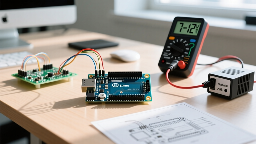
According to the official Arduino Uno R3 documentation, the recommended input voltage range via the barrel jack or VIN pin is 7V to 12V. The absolute limits are 6V to 20V. However, treating these absolute limits as operational guidelines is a common engineering mistake that leads to thermal throttling, brownouts, and catastrophic component failure. To determine if the Uno is suitable for your specific robotics, IoT, or data-logging project, we must analyze the thermodynamics of linear regulation.
The Thermodynamics of Linear Regulation
Unlike switching regulators (buck converters) that efficiently step down voltage by rapidly switching current, an LDO operates by burning off excess voltage as heat. The power dissipated by the regulator is calculated using the formula:
Pd = (Vin - Vout) × I
Where Pd is power dissipated, Vin is input voltage, Vout is 5V, and I is current draw.
The SOT-223 package of the NCP1117 has a junction-to-ambient thermal resistance ($\theta_{JA}$) of approximately 100°C/W without a dedicated heatsink. If you power your Uno with a 12V lead-acid battery and draw just 150mA (common when adding a basic sensor shield and an LCD display), the regulator dissipates 1.05W. This results in a temperature rise of roughly 105°C above ambient room temperature. The silicon junction will quickly exceed 125°C, triggering the internal thermal shutdown protection and causing your microcontroller to randomly reboot.
Project Suitability Matrix by Power Source
To help you match your power source to your project requirements, the following matrix breaks down the real-world suitability of various input voltages for the Arduino Uno R3.
| Power Source | Nominal Vin | Max Safe Current | Thermal Impact | Ideal Project Application |
|---|---|---|---|---|
| USB Type-B | 5.0V | 500mA (Polyfuse limit) | None (Bypasses LDO) | Desktop prototyping, basic IoT nodes |
| 5V Wall Adapter (via 5V Pin) | 5.0V | 1.0A+ (Source dependent) | None (Bypasses LDO) | High-current robotics, LED matrices |
| 6V Alkaline Pack (4x AA) | 6.0V | 200mA | Minimal | Low-power data loggers (Edge of dropout) |
| 7.4V LiPo (2S) | 7.4V - 8.4V | 350mA | Moderate | RC vehicles, mobile rovers |
| 9V Alkaline Battery | 9.0V | 100mA (Voltage sag) | High | Not recommended (Poor capacity, high heat) |
| 12V Wall Adapter | 12.0V | 150mA | Severe | Stationary relays, basic home automation |
Evaluating Edge Cases and Failure Modes
When conducting a project suitability analysis, you must account for edge cases. The ATmega328P datasheet outlines specific Brown-out Detection (BOD) thresholds, typically set to 4.3V for 16MHz operation. Here is how the Uno behaves at the extremes of the input voltage spectrum.
The Under-Voltage Risk (6V via Barrel Jack)
Supplying exactly 6V to the barrel jack is technically within the absolute limits, but highly problematic. The NCP1117 has a dropout voltage of roughly 1.1V at full load. This means 6V in yields a maximum of 4.9V out. As the ATmega328P draws current spikes during EEPROM writes or when driving digital pins high, the voltage rail can dip below the 4.3V BOD threshold, causing erratic resets. Furthermore, at voltages below 6.6V, the onboard comparator that switches between USB and external power may fail to trigger, leading to a backfeed condition where 5V from the barrel jack is pushed backward into your computer's USB port, potentially damaging your PC's motherboard.
The Over-Voltage Risk (15V+ via VIN)
While the board's schematic shows capacitors rated for 16V or 25V, pushing 15V or higher into the VIN pin is a recipe for disaster in high-current applications. The polyfuse (Bourns RXE050) on the board is rated to trip at 500mA, but it only protects the USB line. If you are pulling 200mA from the 5V rail with a 15V input, the LDO is burning 2W of heat. As detailed in SparkFun's comprehensive power guide, this will rapidly degrade the LDO's silicon, eventually causing it to fail in a "short" state, sending 15V directly to the ATmega328P and instantly destroying the microcontroller.
High-Current Robotics: Bypassing the Regulator
If your project suitability analysis reveals that you need to drive multiple servos, high-brightness LED strips, or motor drivers, the Uno's onboard LDO is entirely unsuitable. Standard hobby servos (like the SG90 or MG996R) can draw 700mA to 2.5A under stall conditions.
The Solution: 5V Pin Injection
For high-current projects, engineers bypass the barrel jack entirely and inject a regulated 5V directly into the 5V header pin on the board. This completely bypasses the NCP1117 and the reverse-polarity protection diode.
- Requirement: You must use a high-quality external buck converter (e.g., LM2596 or MP1584EN module) capable of delivering 3A+.
- Warning: Never connect a USB cable to the Uno while injecting 5V into the 5V pin. The lack of a hardware interlock means two 5V sources will fight each other, potentially frying the USB-to-serial ATmega16U2 chip.
- Grounding: Ensure the ground of your external 5V power supply is tied directly to one of the Uno's GND pins to establish a common reference plane for your logic signals.
Modern Alternatives: The 2026 Design Landscape
While the Uno R3 remains a staple in education and legacy systems, modern project suitability analyses in 2026 frequently point toward the Arduino Uno R4 for demanding industrial and automotive applications. The R4 architecture replaces the linear LDO with a highly efficient switching buck converter. This allows the R4 to accept an input voltage of up to 24V directly via the VIN pin without suffering the catastrophic thermal penalties of the R3.
If your project involves 12V or 24V industrial PLCs, automotive telemetry, or high-voltage solar charge controllers, the Uno R4 (or a dedicated 24V-tolerant PLC shield) is vastly superior. However, for low-cost, low-power educational nodes running on 7.4V LiPo batteries, the classic R3's input voltage characteristics remain perfectly adequate when paired with proper thermal management and current budgeting.
Final Engineering Checklist
Before finalizing your PCB or wiring harness, run through this quick power checklist:
- Calculate Total Current: Sum the quiescent and peak current of the MCU, sensors, and communication modules (e.g., ESP-01 Wi-Fi modules can spike to 300mA during transmission).
- Select the Right Topology: If total 5V current exceeds 300mA and your input voltage is above 9V, abandon the barrel jack and use an external buck converter to the 5V pin.
- Verify Battery Sag: If using chemical cells, measure the voltage under load. A "9V" alkaline battery often sags to 6.5V under a 150mA load, pushing the Uno into brownout territory.
- Check Thermal Limits: If operating in an enclosed 3D-printed ABS/PETG case, ambient temperature inside the enclosure can easily reach 50°C, drastically reducing the safe current limit of the onboard LDO.