
Introduction to Microcontroller Programming
Writing your first program for Arduino Uno is a rite of passage for electronics enthusiasts, engineers, and students alike. In the Arduino ecosystem, a program is officially referred to as a sketch. Whether you are automating a greenhouse, building a custom macro keyboard, or simply trying to make an LED blink, understanding the foundational workflow of the Arduino IDE and the C++ based syntax is critical.
This comprehensive beginner guide will walk you through the exact hardware requirements, software setup, and coding syntax needed to successfully compile and upload a sketch to your board. We will also cover the underlying electronics theory that most tutorials skip, ensuring you build safe and reliable circuits from day one.
Hardware Requirements (2026 Edition)
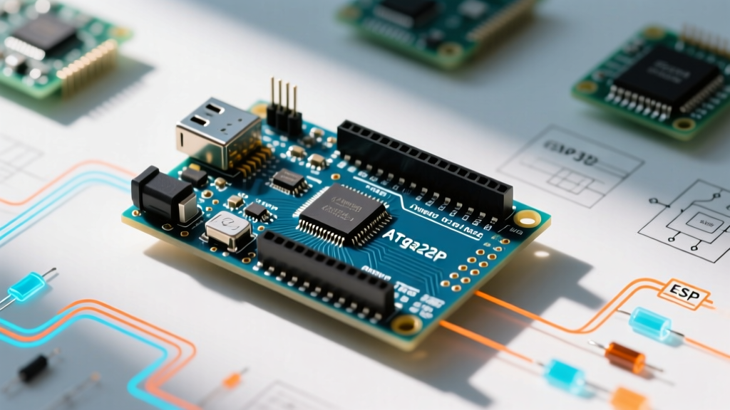
Before writing any code, you need the right physical tools. While the classic Uno R3 remains a staple, the newer R4 series has become the standard for modern projects.
- The Microcontroller: An Arduino Uno R3 (featuring the ATmega328P chip, typically ~$27.50) or the newer Uno R4 Minima (featuring a 32-bit Renesas RA4M1 ARM Cortex-M4, ~$19.99). Both are fully compatible with standard shields and beginner sketches.
- USB Cable: A high-quality USB Type-A to Type-B cable for the R3, or a USB-C cable for the R4. Critical Note: Ensure the cable supports data transfer. Many cheap cables are 'charge-only' and will power the board but fail to upload your program.
- Components: One standard 5mm Red LED and one 220Ω (Ohm) through-hole resistor.
- Breadboard & Jumper Wires: A standard half-size solderless breadboard and male-to-male jumper wires.
Step 1: Setting Up the Arduino IDE
To translate your human-readable code into machine code (hex) that the microcontroller understands, you need an Integrated Development Environment (IDE). As of 2026, Arduino IDE 2.3.x is the recommended desktop application, offering modern features like autocompletion, real-time error linting, and a live serial plotter.
- Download the IDE from the official Arduino IDE v2 documentation page.
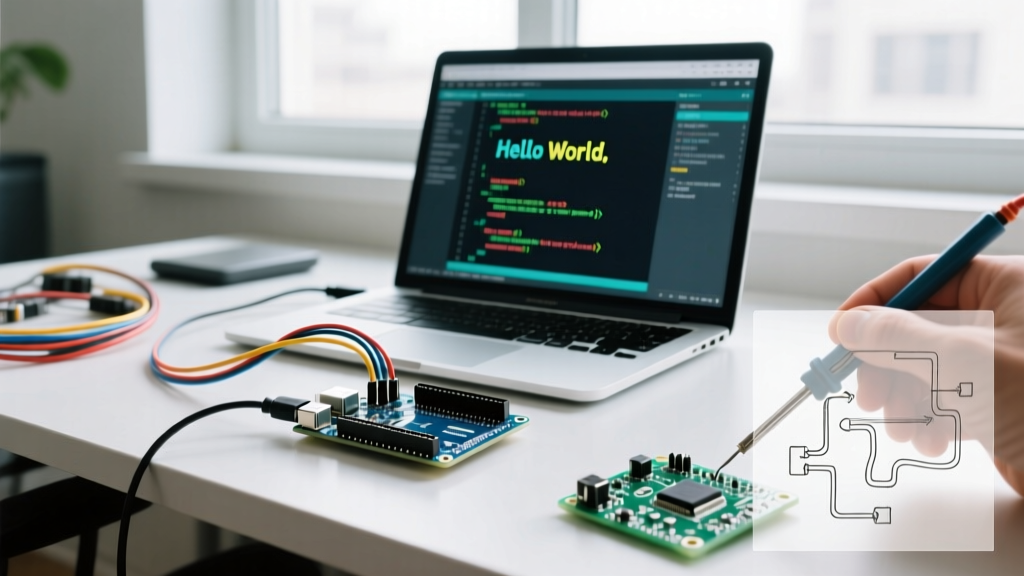
- Install the software and launch it. Connect your Uno to your computer via USB.
- Navigate to Tools > Board and select Arduino Uno (or Arduino Uno R4 Minima if applicable).
- Navigate to Tools > Port and select the COM port (Windows) or /dev/tty.usbmodem (macOS) that appeared when you plugged in the board.
Step 2: Anatomy of an Arduino Sketch
Every program for Arduino Uno relies on two mandatory C++ functions. Understanding these is non-negotiable for moving past beginner tutorials.
The setup() Function
This block of code runs exactly once when the board is powered on or reset. It is used to initialize variables, configure pin modes (input vs. output), and start communication libraries like Serial or I2C.
The loop() Function
Immediately after setup() finishes, the loop() function begins. As the name implies, it runs continuously, infinitely, until the board loses power. This is where your main logic, sensor reading, and actuator control happen.
Step 3: Writing the Code and Electronics Theory
Let us write a sketch that blinks an external LED connected to Digital Pin 8. But first, let us address the electronics theory that prevents you from burning out your components.
Why a 220Ω Resistor?
A standard red LED has a forward voltage drop of roughly 2.0V and a maximum safe continuous current of 20mA (0.02A). The Arduino Uno's digital pins output 5V. If you connect the LED directly to the 5V pin, it will draw excessive current, overheat, and permanently fail (often taking the microcontroller's GPIO pin with it). We use Ohm's Law to calculate the required resistor:
R = (V_source - V_LED) / I_LED
R = (5V - 2.0V) / 0.02A = 150Ω
While 150Ω is the mathematical minimum, using a standard 220Ω or 330Ω resistor is best practice. It slightly dims the LED but drastically extends its lifespan and reduces thermal stress on the ATmega328P's internal silicon.
The Sketch
Copy the following code into your IDE:
// Define the pin connected to the LED
const int LED_PIN = 8;

void setup() {
  // Initialize digital pin 8 as an output
  pinMode(LED_PIN, OUTPUT);

  // Start Serial communication for debugging at 9600 baud
  Serial.begin(9600);
  Serial.println("System Initialized. Starting Blink Sequence.");
}

void loop() {
  digitalWrite(LED_PIN, HIGH);  // Turn the LED on (5V)
  Serial.println("LED State: ON");
  delay(1000);                  // Wait for 1000 milliseconds (1 second)

  digitalWrite(LED_PIN, LOW);   // Turn the LED off (0V)
  Serial.println("LED State: OFF");
  delay(1000);                  // Wait for 1 second
}
Step 4: Compilation and Uploading
Click the Upload button (the right-facing arrow icon) in the top left corner of the IDE. The software will first verify (compile) the code, checking for syntax errors. If successful, it uses avrdude (for the R3) or bossac (for the R4) to push the compiled binary to the board's flash memory.
Once uploaded, open the Serial Monitor (magnifying glass icon) and set the baud rate to 9600. You should see the "LED State" messages printing every second, perfectly synced with your physical LED.
Troubleshooting Common Upload Errors
Beginners frequently encounter upload failures. Use this diagnostic matrix to solve them quickly.
| Error Message / Symptom | Root Cause | Actionable Solution |
|---|---|---|
avrdude: stk500_getsync() attempt 10 of 10 |
The IDE cannot communicate with the bootloader. Often caused by selecting the wrong board or port. | Verify Tools > Port. Unplug the USB, wait 5 seconds, and replug. Ensure no other software (like Cura or 3D printers slicers) is hogging the COM port. |
| Port option is greyed out / missing | Using a 'charge-only' USB cable, or missing drivers for a clone board. | Swap to a verified data-sync USB cable. If using a $6 clone Uno, download and install the CH340/CH341 USB-Serial drivers for your OS. |
Board at COM3 is not available |
The microcontroller crashed or the USB hub suspended power to save energy. | Press the physical red 'RESET' button on the Uno right before clicking Upload. Change Windows USB Selective Suspend settings to 'Disabled'. |
Compilation Error: expected ';' before '}' |
Syntax error in your C++ code. Missing a semicolon at the end of a statement. | Check the line number indicated in the red console output. Add the missing semicolon. Remember that C++ is case-sensitive (PinMode will fail, pinMode is correct). |
Pro-Tip: Moving Beyond delay()
While the delay() function is excellent for a first program, it is a 'blocking' function. When the Arduino is delaying, it cannot read buttons, monitor sensors, or update displays. As you progress, research the BlinkWithoutDelay example built into the IDE (File > Examples > 02.Digital > BlinkWithoutDelay). It uses the millis() function to track time without pausing the processor, a fundamental concept for advanced multitasking in embedded systems.
Next Steps for Your Uno
Now that you have successfully written and uploaded your first program for Arduino Uno, you have unlocked the gateway to physical computing. Your next logical steps should include:
- Reading Inputs: Wire a tactile push-button to a digital pin using
INPUT_PULLUPto control your LED. - Analog Sensors: Connect a photoresistor (LDR) to an Analog pin (A0-A5) to make your LED turn on automatically when the room gets dark.
- PWM Fading: Move your LED to a pin marked with a tilde (~) like Pin 9, and use the
analogWrite()function to create a smooth breathing effect.
By mastering these foundational steps, you transition from simply copying code to actively engineering custom electronic solutions.