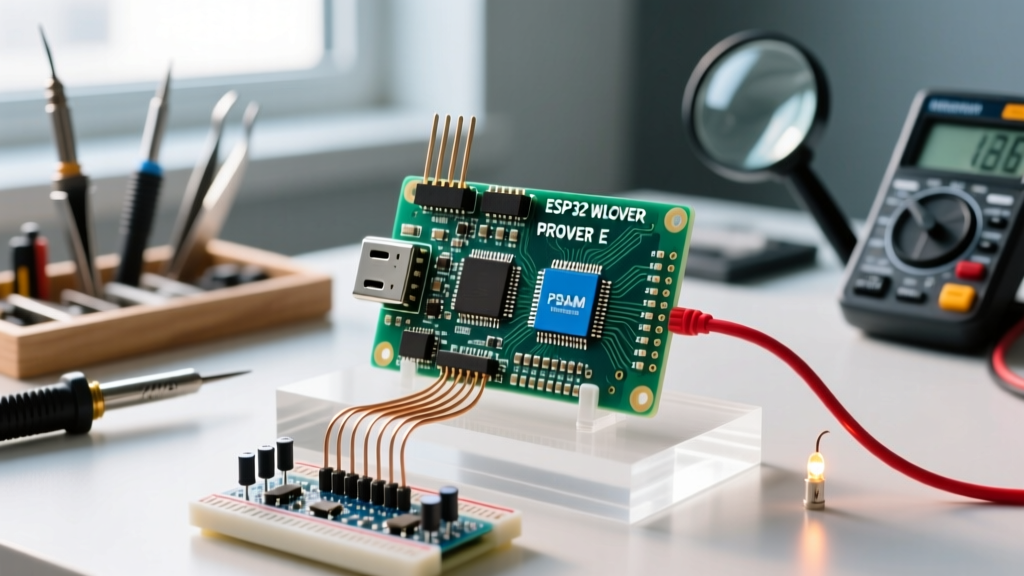

Why Choose the ESP32-WROVER-E Over Standard WROOM?
If you are transitioning from basic microcontrollers to advanced IoT projects, you have likely encountered the standard ESP32-WROOM-32. While the WROOM is a fantastic entry point, it caps out at 520KB of usable SRAM. When your project requires audio buffering, camera image processing, or complex TLS encryption, that memory vanishes instantly. This is where the ESP32-WROVER-E steps in.
The WROVER-E module integrates an external 8MB PSRAM (Pseudo-Static RAM) alongside the standard 520KB internal SRAM and 16MB of Flash memory. As of 2026, the 'E' variant is the industry standard for hobbyists and prototypers, replacing the older WROVER-B and WROVER-D modules by offering improved Wi-Fi TX power and better thermal stability. According to the official Espressif module documentation, the WROVER-E maintains pin compatibility with standard WROOM layouts while routing GPIO 16 and GPIO 17 to the external PSRAM chip.
Hardware Selection and 2026 Pricing
Before diving into the software, you need the right development board. Bare WROVER-E modules require complex RF impedance matching and 3.3V LDO regulation, which is not beginner-friendly. Instead, purchase a development board that breaks out the pins to standard 0.1-inch headers.
- Generic DevKitC V4 WROVER-E: The most common and affordable option. Features a CP2102 or CH340 USB-to-UART bridge, dual micro-USB or USB-C ports (depending on the revision), and an onboard AMS1117-3.3 voltage regulator. Price range: $9.50 to $13.00.
- Freenove ESP32-WROVER Dev Board: Includes an integrated camera connector (OV2640) and a breadboard-friendly layout. Excellent if you plan to use the PSRAM for image buffering. Price range: $18.00 to $24.00.
- Espressif ESP-WROVER-KIT V4.1: The official development kit with an integrated LCD, microSD slot, and JTAG header. Overkill for simple projects but ideal for deep debugging. Price range: $45.00 to $60.00.
Step-by-Step ESP32 WROVER E Arduino IDE Setup
Programming the ESP32 WROVER E Arduino environment requires the official Espressif core. As of 2026, the Arduino ESP32 Core v3.x is the standard, offering full support for the WROVER-E's memory architecture and Wi-Fi 4 stack.
- Install Arduino IDE: Download the latest Arduino IDE v2.x from the official Arduino website.
- Add Board Manager URL: Navigate to File > Preferences. In the "Additional boards manager URLs" field, paste:
https://raw.githubusercontent.com/espressif/arduino-esp32/gh-pages/package_esp32_index.json - Install the Core: Open the Boards Manager (icon on the left sidebar), search for
esp32, and install the latest v3.x package by Espressif Systems. - Select Your Board: Go to Tools > Board > esp32 and select ESP32 Dev Module (for generic DevKitC boards) or ESP32 WROVER Kit (if using the official Espressif board).
- Select Port and Speed: Choose your COM port. Set the "Upload Speed" to
921600for faster flashing. If you experience upload failures, drop this to115200.
Configuring PSRAM: The QSPI vs. OPI Trap
This is the most critical step where beginners fail. The ESP32-WROVER-E uses QSPI PSRAM (Quad SPI). Its sibling, the WROVER-IE, uses OPI PSRAM (Octal SPI). If you select the wrong PSRAM mode in the Arduino IDE, your code will compile, but the board will experience a Guru Meditation Error (core panic) upon booting because the memory controller cannot communicate with the RAM chip.
To configure this correctly for the WROVER-E:
- Go to Tools > PSRAM in the Arduino IDE menu.
- Select QSPI PSRAM. (Do not select OPI PSRAM unless you are certain you have a WROVER-IE module).
- Set Flash Size to 16MB (128Mb).
- Set Partition Scheme to Huge APP (3MB No OTA/1MB SPIFFS) to maximize your code storage space.
Testing Your PSRAM Allocation
Once your ESP32 WROVER E Arduino setup is complete, you must verify that the IDE is actually utilizing the 8MB of external memory. The internal heap is used by default; you must explicitly instruct the ESP32 to allocate large buffers to the PSRAM.
Upload the following diagnostic sketch to your board:
#include <Arduino.h>

void setup() {
  Serial.begin(115200);
  delay(2000); // Wait for serial monitor connection

  Serial.println("--- ESP32 WROVER-E Memory Diagnostic ---");

  // Check if PSRAM is initialized
  if(psramFound()) {
    Serial.printf("PSRAM Detected! Size: %u bytes\n", ESP.getPsramSize());
    Serial.printf("Free PSRAM: %u bytes\n", ESP.getFreePsram());

    // Allocate a 2MB buffer in PSRAM
    uint8_t* largeBuffer = (uint8_t*)ps_malloc(2 * 1024 * 1024);
    if(largeBuffer) {
      Serial.println("SUCCESS: 2MB buffer allocated in PSRAM.");
      free(largeBuffer);
    } else {
      Serial.println("FAILURE: Could not allocate 2MB in PSRAM.");
    }
  } else {
    Serial.println("ERROR: PSRAM not found! Check your IDE Tools settings.");
  }

  Serial.printf("Free Internal SRAM: %u bytes\n", ESP.getFreeHeap());
}

void loop() {
  // Empty loop
}
Open the Serial Monitor at 115200 baud. A successful WROVER-E setup will report approximately 8,388,608 bytes (8MB) of total PSRAM size.
The Strapping Pin Hazard: GPIO 12
When wiring sensors to your ESP32 WROVER E Arduino project, you must respect the "strapping pins." These pins dictate the boot behavior of the chip. GPIO 12 (MTDI) is the most notorious for beginners.
On the ESP32, GPIO 12 determines the flash voltage. If GPIO 12 is pulled HIGH during boot, the ESP32 expects the internal SPI flash to operate at 1.8V. However, almost all WROVER-E modules use 3.3V flash. If you connect a sensor that pulls GPIO 12 high on startup, your board will enter an endless boot loop, printing flash read err, 1000 to the serial monitor.
Actionable Advice: Never use GPIO 12 for inputs that might be high during power-on. If you absolutely must use GPIO 12, you can use the espefuse.py tool to burn the XPD_SDIO_TIEH, XPD_SDIO_FORCE, and XPD_SDIO_REG efuses to permanently force 3.3V flash operation, ignoring the GPIO 12 state. However, this is a one-way hardware modification and is not recommended for beginners.
Troubleshooting Matrix: Boot Failures and Brownouts
Working with high-power Wi-Fi modules introduces power delivery challenges. Use this matrix to diagnose common ESP32 WROVER E Arduino hardware and software failures.
| Symptom / Serial Output | Root Cause | Solution |
|---|---|---|
rst:0xc (SW_CPU_RESET) looping |
PSRAM configuration mismatch (OPI vs QSPI) or GPIO 12 pulled high. | Change IDE setting to QSPI PSRAM. Remove any pull-up resistors on GPIO 12. |
Brownout detector was triggered |
Wi-Fi TX spike draws up to 450mA, collapsing the USB port voltage below 2.4V. | Use a dedicated 5V/2A power supply wired to the 5V and GND pins. Do not rely on laptop USB ports. |
| Upload fails at 100% or "Timed out waiting for packet header" | Auto-reset circuit failing to pull GPIO 0 LOW and toggle EN. | Hold the "BOOT" button on the dev board while clicking "Upload" in the IDE. Release when it says "Connecting...". |
| PSRAM reports 4MB instead of 8MB | Using an older ESP32 Arduino Core (v1.x or early v2.x) with incorrect cache mapping. | Update to the latest v3.x ESP32 Core via the Boards Manager. |
Pro-Tip for Powering WROVER-E Projects: The onboard AMS1117-3.3 LDO found on cheap DevKitC boards has a maximum output of 800mA and suffers from severe thermal throttling. If your project uses the Wi-Fi radio continuously alongside an external sensor (like an I2C OLED or SD card module), the LDO will overheat and drop voltage, causing random reboots. For permanent installations, bypass the onboard LDO entirely by feeding a clean, external 3.3V supply directly into the 3V3 pin, ensuring your external regulator can handle at least 1A.
Summary
Mastering the ESP32 WROVER E Arduino workflow unlocks massive memory headroom for advanced DIY electronics. By understanding the critical differences in PSRAM architecture (QSPI vs OPI), respecting the strapping pin limitations, and providing robust power delivery, you can build stable, memory-intensive IoT nodes, audio streamers, and camera arrays without hitting the internal SRAM ceiling. Always verify your memory allocation via the Serial Monitor before deploying complex logic, and ensure your power supply can handle the 450mA Wi-Fi transmission spikes inherent to the ESP32 architecture.