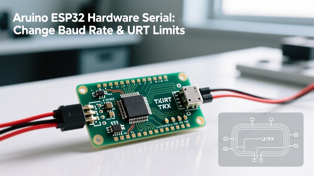

The UART Bottleneck: Why Baud Rate Mastery Matters in 2026
Serial communication remains the undisputed backbone of hardware debugging, GPS parsing, and industrial sensor interfacing. While wireless protocols like Wi-Fi 6 and BLE 5.3 dominate IoT data transmission, the underlying hardware UART (Universal Asynchronous Receiver-Transmitter) is what keeps your microcontroller tethered to reality. For developers transitioning from legacy 8-bit AVR architectures to 32-bit dual-core powerhouses, understanding the nuances of serial configuration is critical.
When engineers need to perform an Arduino ESP32 hardware serial change baud rate operation mid-execution—perhaps to switch from a low-speed debug console to a high-speed binary data dump—they often encounter FIFO buffer overruns or clock drift issues. This guide dissects the ESP32 UART architecture, provides exact implementation strategies, and compares its serial capabilities against the Arduino Mega 2560 and STM32 Nucleo platforms.
Arduino ESP32 Hardware Serial Architecture
The original ESP32 (Xtensa LX6 dual-core) and the newer ESP32-S3 (Xtensa LX7) feature three dedicated hardware UART controllers: UART0, UART1, and UART2. Unlike the Arduino Uno, which hardwires its single hardware serial port to GPIO 0 and 1, the ESP32 utilizes a highly flexible GPIO Matrix. This allows you to map any UART peripheral to almost any available GPIO pin, bypassing the rigid pinouts of older microcontrollers.
Peripheral Breakdown & Pin Mapping
- UART0: Hardwired by default to the USB-to-UART bridge (e.g., CP2102N or CH340) on development boards. Used for the Serial Monitor and flashing firmware. Default pins: GPIO 1 (TX) and GPIO 3 (RX).
- UART1: On early ESP32-WROOM modules, UART1 was partially consumed by the SPI flash memory (GPIO 9/10). However, using the GPIO matrix, it is routinely remapped to GPIO 17 (TX) and GPIO 16 (RX) for external hardware serial communication.
- UART2: Completely free for general-purpose hardware serial communication. Default pins: GPIO 17 (TX) and GPIO 16 (RX) on some dev kits, but easily remapped.
Expert Insight: Never attempt to use UART1 on an ESP32-WROOM-32E without remapping it. The default GPIO 9 and 10 are tied to the internal flash SPI bus. Transmitting serial data on these pins will corrupt your firmware and cause a kernel panic. Always use
HardwareSerialwith explicit pin definitions.
Step-by-Step: How to Change Baud Rate on ESP32 Hardware Serial
In the Arduino IDE environment, the ESP32 core handles serial initialization via the HardwareSerial class. While Serial.begin(baudrate) is standard, dynamically changing the baud rate after initialization requires specific methods to prevent bus locking.
Dynamic Baud Rate Switching Implementation
If your application requires shifting from a 9600 baud GPS NMEA sentence parser to a 921600 baud binary firmware update mode, you must flush the buffers before switching. The ESP32 Arduino core provides the updateBaudRate() function for this exact scenario.
According to the official Arduino Serial Reference, re-initializing Serial.begin() can sometimes cause memory leaks or race conditions in RTOS-based environments like FreeRTOS, which the ESP32 runs natively. Instead, use the update method:
#include <HardwareSerial.h>

// Initialize UART2 on custom pins
HardwareSerial MySerial(2);

void setup() {
  // Start at standard GPS baud rate
  MySerial.begin(9600, SERIAL_8N1, 16, 17);
}

void loop() {
  if (triggerHighSpeedMode()) {
    // 1. Flush existing buffers to prevent data corruption
    MySerial.flush();
    // 2. Safely change the baud rate without full re-initialization
    MySerial.updateBaudRate(921600);

    // Transmit high-speed binary payload
    MySerial.write(binaryPayload, payloadSize);
  }
}
Standard vs. Custom Baud Rates & The APB Clock
The ESP32 derives its UART baud rate from the APB (Advanced Peripheral Bus) clock, which typically runs at 80 MHz. The hardware uses a 20-bit fractional divider to generate the baud rate. While standard rates (9600, 115200) have near-zero error margins, arbitrary custom rates can introduce sampling errors.
| Target Baud Rate | Calculated Divider (80MHz) | Actual Error Margin | Reliability Verdict |
|---|---|---|---|
| 9600 | 833.33 | < 0.1% | Flawless (Long distance) |
| 115200 | 69.44 | < 1.5% | Standard (Reliable) |
| 921600 | 8.68 | ~2.1% | Good (Short traces/wires) |
| 2,000,000 | 4.00 | 0.0% | Excellent (Requires USB-UART bridge support) |
| 3,500,000 | 2.28 | > 4.5% | High Failure Risk (FIFO Overruns) |
For exhaustive details on the ESP32 UART fractional divider and FIFO thresholds, refer to the Espressif ESP-IDF UART API Documentation.
Board Comparison: ESP32 vs. Arduino Mega 2560 vs. STM32F4
How does the ESP32 stack up against traditional workhorses when handling high-speed serial data? Below is a 2026 hardware comparison matrix focusing on UART capabilities, buffer sizes, and logic levels.
| Feature | ESP32-WROOM-32E (~$2.50) | Arduino Mega 2560 Rev3 (~$45.00) | STM32 Nucleo-F446RE (~$22.00) |
|---|---|---|---|
| Hardware UARTs | 3 (Plus 1 USB-CDC on S3) | 4 | 6 (USART/UART) |
| Max Theoretical Baud | 5 Mbps (APB/16) | 2 Mbps (Limited by 16MHz clock) | 10.5 Mbps (APB2 bus) |
| RX/TX FIFO Buffer | 128 Bytes (Hardware) | 64 Bytes (Software/Serial) | 1 Byte (Relies on DMA/Interrupts) |
| Pin Remapping | Yes (GPIO Matrix) | No (Hardwired) | Yes (Alternate Function Mux) |
| Logic Level | 3.3V (Not 5V tolerant) | 5V | 3.3V (Select pins 5V tolerant) |
| RTOS Integration | Native FreeRTOS (Uart driver) | Bare-metal / Arduino Core | FreeRTOS / Zephyr / Bare-metal |
The Arduino Mega 2560 wins purely on the number of hardware ports (4), but its 16 MHz ATmega2560 clock severely limits maximum baud rates and lacks the hardware FIFO depth of the ESP32. The STM32F4 offers superior raw speed (10.5 Mbps) but requires complex HAL/DMA configuration to prevent data loss, whereas the ESP32's 128-byte hardware FIFO provides a massive safety net for burst data handling.
Real-World Edge Cases & Hardware Failure Modes
Software configuration is only half the battle. When pushing ESP32 hardware serial beyond 115200 baud, physical layer limitations emerge. Here are the most common failure modes encountered in industrial and advanced DIY deployments:
1. The USB-to-UART Bridge Bottleneck
You can configure the ESP32 to transmit at 3 Mbps, but if your development board uses a cheap CH340G USB-to-UART chip, the data will bottleneck or corrupt. The CH340 maxes out around 2 Mbps in optimal conditions. For high-speed serial logging, ensure your dev board uses a Silicon Labs CP2102N or an FTDI FT232RL, both of which comfortably support 3 Mbps and feature advanced driver buffering on Windows/Linux hosts.
2. Logic Level Shifting & Capacitance
The ESP32 operates at 3.3V logic. Interfacing it with 5V legacy equipment (like older RS-232 transceivers or 5V Arduinos) requires a level shifter. However, standard BSS138-based bi-directional level shifters introduce parasitic capacitance that destroys signal integrity above 460800 baud.
For high-speed 3.3V to 5V translation, use dedicated push-pull level translators like the TI SN74AVCH4T245. These chips support data rates up to 100 Mbps and maintain the sharp square-wave edges required for high-baud UART sampling.
3. Cable Length and Ground Loops
UART is an unbalanced, single-ended protocol. At 921600 baud, the bit duration is roughly 1.08 microseconds. A standard 2-meter unshielded jumper wire acts as an antenna, picking up EMI from nearby switching power supplies.
Rule of Thumb: Keep raw UART traces/wires under 50cm for baud rates exceeding 1 Mbps. For longer distances, you must convert the UART signal to RS-485 using a differential transceiver like the MAX485, which can reliably push serial data up to 1200 meters at lower baud rates.
Expert Troubleshooting Matrix
Use this diagnostic matrix when your serial output degrades after a baud rate change.
| Symptom | Probable Cause | Hardware/Software Fix |
|---|---|---|
| Garbage characters (e.g., '??') | Baud rate mismatch or APB clock drift. | Verify host terminal matches exact ESP32 rate. Check if Wi-Fi/BT is causing APB clock throttling. |
| Missing chunks of data | FIFO Overrun (Software too slow to read). | Increase RX buffer size in Serial.setRxBufferSize(1024) or implement DMA. |
| Intermittent framing errors | Signal edge degradation / Parasitic capacitance. | Replace passive BSS138 level shifters with active TI SN74AVCH4T245. Shorten wire length. |
| Kernel Panic / Reboot on TX | UART1 mapped to SPI Flash pins (GPIO 9/10). | Remap UART1 to GPIO 16/17 or switch to UART2. |
Final Verdict for Hardware Engineers
The ESP32 remains a powerhouse for serial communication, provided you respect its hardware boundaries. The ability to execute an Arduino ESP32 hardware serial change baud rate dynamically via updateBaudRate() is a massive advantage for multi-mode IoT devices. However, always pair your software configuration with the correct physical layer components—specifically high-speed USB bridges and active logic level translators. By treating the physical wiring with the same rigor as your C++ code, you can reliably push the ESP32 to its 3 Mbps practical limits without dropping a single byte.