
Why the ESP32-C3 Super Mini is Dominating IoT Prototyping
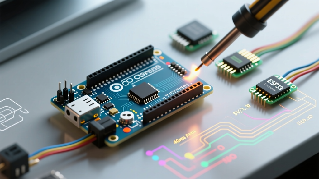
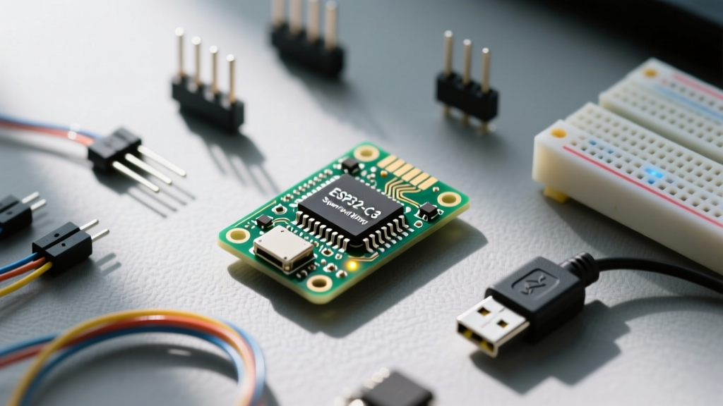
The ESP32-C3 Super Mini has rapidly become the go-to development board for engineers and hobbyists who need Wi-Fi and Bluetooth 5.0 (BLE) capabilities in a footprint smaller than a postage stamp. Priced often under $4, this board leverages the Espressif ESP32-C3FH4 SoC. Unlike older ESP8266 modules or the dual-core ESP32 DevKit V1, the C3 variant utilizes a 32-bit RISC-V single-core processor clocked at 160 MHz. It features 4MB of internal SPI flash, eliminating the need for an external flash chip and drastically reducing the physical board size.
However, its ultra-compact 'Super Mini' form factor introduces specific hardware quirks—particularly regarding USB-to-UART bridging and boot mode entry—that can frustrate beginners. This guide bypasses the common pitfalls, configures your toolchain correctly, and deploys a real-world Wi-Fi scanning project to verify your hardware.
Hardware Teardown: Specs and Form Factor Quirks
Before writing a single line of code, you must understand the physical limitations and advantages of the Super Mini layout. Most generic 'Super Mini' boards on the market expose 14 GPIO pins and utilize castellated edges or standard 0.1-inch header spacing.
| Feature | ESP32-C3 Super Mini | Standard ESP32 DevKit V1 |
|---|---|---|
| Architecture | RISC-V Single-Core (160MHz) | Xtensa LX6 Dual-Core (240MHz) |
| Wireless | Wi-Fi 4 + BLE 5.0 | Wi-Fi 4 + Classic BT + BLE 4.2 |
| Flash Memory | 4MB (Internal SIP) | 4MB (External SPI) |
| USB Interface | Native USB-JTAG / UART | CP2102 / CH340 External Bridge |
| ADC Channels | 6 (12-bit, SAR) | 18 (12-bit, SAR) |
| Onboard LED | GPIO 8 (Usually Active LOW) | GPIO 2 (Active HIGH) |
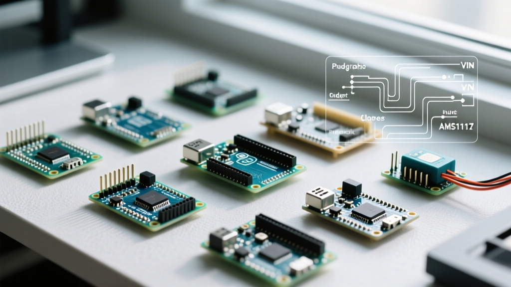
Note: Always verify your specific board's LED pin. While the official Espressif devkits use GPIO 2, the vast majority of third-party Super Mini clones route the onboard blue LED to GPIO 8.
The Boot Mode Bottleneck (And How to Bypass It)
The most common failure point for new users is the 'Failed to connect to ESP32-C3: Timed out waiting for packet header' error in the Arduino IDE. This happens because the Super Mini's ultra-low-cost manufacturing often omits the DTR/RTS auto-reset transistor circuit found on larger dev boards.
To flash code, the ESP32-C3 must be manually forced into the serial bootloader. You must perform the GPIO9 Dance:
- Locate the BOOT button (connected to GPIO9) and the RESET button (connected to EN/GPIO8).
- Press and hold the BOOT button.
- While holding BOOT, press and release the RESET button.
- Release the BOOT button.
- Immediately click 'Upload' in your IDE.
Pro-Tip: If your board features a native USB-C connection directly to GPIO18/19 (USB-JTAG), you may not need to do this every time once the initial firmware with USB-CDC support is flashed. However, for the very first bare-metal flash, the manual boot sequence is mandatory.
Toolchain Configuration: Arduino IDE 2.x Setup
The ESP32-C3 requires the official Espressif Arduino Core. Do not use outdated third-party board managers. Navigate to File > Preferences and add the following URL to your Additional Boards Manager URLs:
https://raw.githubusercontent.com/espressif/arduino-esp32/gh-pages/package_esp32_index.json
Search for 'esp32' in the Boards Manager and install the latest version. For a comprehensive understanding of the underlying core, refer to the official Arduino-ESP32 GitHub repository.
Critical Menu Settings for the Super Mini
Select ESP32C3 Dev Module from the board list. You must configure the following tools menu settings to ensure serial communication works over the USB port:
- USB CDC On Boot: Enabled (Crucial: Without this, Serial.print outputs to hardware UART pins, not your USB screen).
- Flash Mode: QIO
- Flash Size: 4MB (32Mb)
- Partition Scheme: Default 4MB with spiffs
- JTAG Adapter: Integrated USB JTAG
First Project: Wi-Fi Environment Scanner & Status Beacon
To verify both the RISC-V core and the 2.4GHz radio antenna, we will build a Wi-Fi network scanner. This project scans for local SSIDs, prints their RSSI (signal strength) to the serial monitor, and pulses the onboard LED to indicate radio activity.
#include

// GPIO 8 is the standard LED pin on most Super Mini clones
const int LED_PIN = 8;

void setup() {
  // Initialize Serial over Native USB-CDC
  Serial.begin(115200);
  delay(2000); // Allow USB-CDC time to enumerate

  pinMode(LED_PIN, OUTPUT);
  digitalWrite(LED_PIN, HIGH); // Turn OFF (Active LOW)

  Serial.println("\n--- ESP32-C3 Super Mini Wi-Fi Scanner ---");

  // Set WiFi to station mode and disconnect from previous APs
  WiFi.mode(WIFI_STA);
  WiFi.disconnect();
  delay(100);
  Serial.println("Wi-Fi Radio Initialized.");
}

void loop() {
  // Pulse LED to indicate scan starting
  digitalWrite(LED_PIN, LOW); // Turn ON
  Serial.println("Scanning for networks...");

  // WiFi.scanNetworks returns the number of networks found
  int n = WiFi.scanNetworks();

  digitalWrite(LED_PIN, HIGH); // Turn OFF

  if (n == 0) {
    Serial.println("No networks found.");
  } else {
    Serial.print(n);
    Serial.println(" networks found:");
    for (int i = 0; i < n; ++i) {
      // Print SSID and RSSI
      Serial.printf("%2d: %s (%d)\n", i + 1, WiFi.SSID(i).c_str(), WiFi.RSSI(i));
      delay(10);
    }
  }
  Serial.println("------------------------");

  // Wait 5 seconds before rescanning
  delay(5000);
}
Code Analysis & RF Considerations
Notice the delay(2000); in the setup() function. Because the ESP32-C3 Super Mini uses native USB-CDC rather than a dedicated hardware UART bridge chip, the USB port requires a moment to enumerate with the host OS upon boot. Skipping this delay often results in the first few lines of serial output being truncated or lost entirely.
Furthermore, the Super Mini utilizes a PCB trace antenna or a small ceramic chip antenna. According to the ESP32-C3 Datasheet, the RF performance is highly dependent on ground plane clearance. Ensure your breadboard or enclosure does not place metal directly beneath the antenna quadrant of the board, or you will see a 10-15dBm drop in RSSI reception.
Power Profiling: Real-World Current Consumption
One of the primary reasons to choose the C3 over the standard ESP32 is power efficiency. The RISC-V architecture and lack of a secondary ULP (Ultra Low Power) co-processor simplify the sleep states. Using a hardware current shunt monitor, here is what you can expect from a bare Super Mini board powered at 3.3V:
| Power State | Configuration | Average Current Draw |
|---|---|---|
| Active TX | Wi-Fi Transmitting (Max Power) | ~135 mA |
| Active RX | Wi-Fi Receiving / Scanning | ~95 mA |
| Modem Sleep | CPU running, Wi-Fi DTIM active | ~25 mA |
| Light Sleep | CPU paused, RTC memory active | ~130 µA |
| Deep Sleep | Only RTC controller powered | ~5 µA |
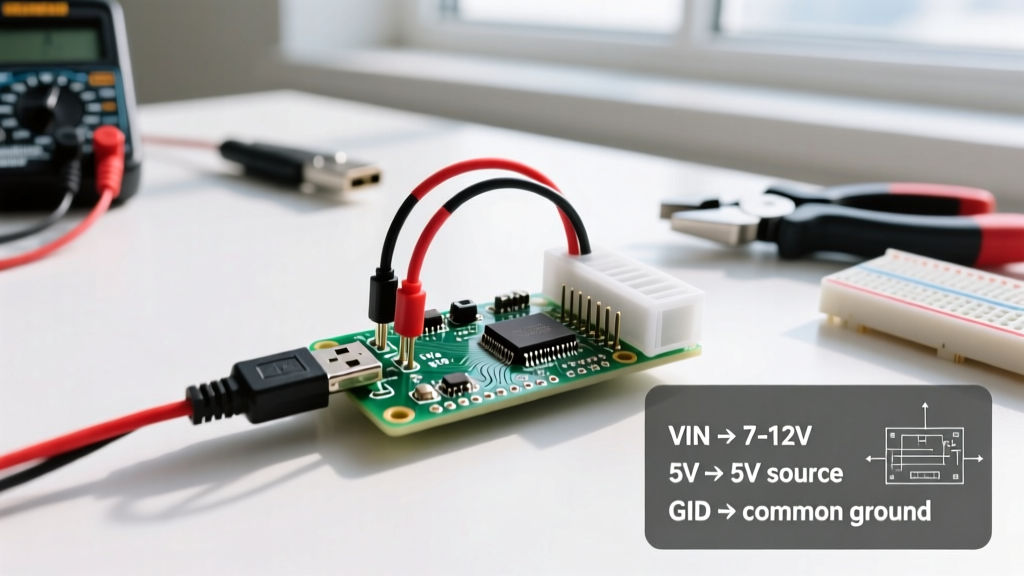
Note: These metrics apply to the bare module. If you are powering the board via the 5V USB pin, the onboard LDO (Low Dropout Regulator) will add a quiescent current overhead of roughly 5-10mA, making Deep Sleep less viable for battery-powered nodes unless you bypass the LDO and feed 3.3V directly to the 3V3 pin.
Pinout Traps and Expansion Limitations
As you move beyond blinking LEDs and scanning Wi-Fi, the ESP32-C3 Super Mini presents specific I/O limitations you must architect around:
1. The ADC Noise Floor
The C3 features a 12-bit SAR ADC, but it is notoriously noisy compared to the ESP32-S3. For precision analog sensing (like load cells or thermistors), you must implement software oversampling (taking 16+ reads and averaging) or use an external I2C ADC like the ADS1115.
2. I2C Pin Selection
Unlike standard Arduino boards, the ESP32-C3 allows you to map I2C to almost any GPIO. However, avoid using GPIO18 and GPIO19 if you are utilizing the native USB port, as these are hardwired to the USB D- and D+ lines. Safe defaults for I2C are SDA on GPIO6 and SCL on GPIO7.
3. 3.3V Logic Strictness
The ESP32-C3 is strictly a 3.3V logic device. While some pins are documented as '5V tolerant' in specific high-impedance input states, feeding 5V into any GPIO configured as an output or during boot will permanently fry the RISC-V silicon. Always use a logic level shifter when interfacing with 5V sensors or standard Arduino shields.
Next Steps
With your toolchain verified and the Wi-Fi radio proven, your ESP32-C3 Super Mini is ready for deployment. The next logical step is integrating the esp_wifi_set_ps(WIFI_PS_MAX_MODEM) function to throttle power consumption, or exploring the ESP-NOW protocol for ultra-low latency, router-less mesh communication between multiple C3 nodes.