
The Appeal (and Quirks) of the ESP32 C3 Super Mini
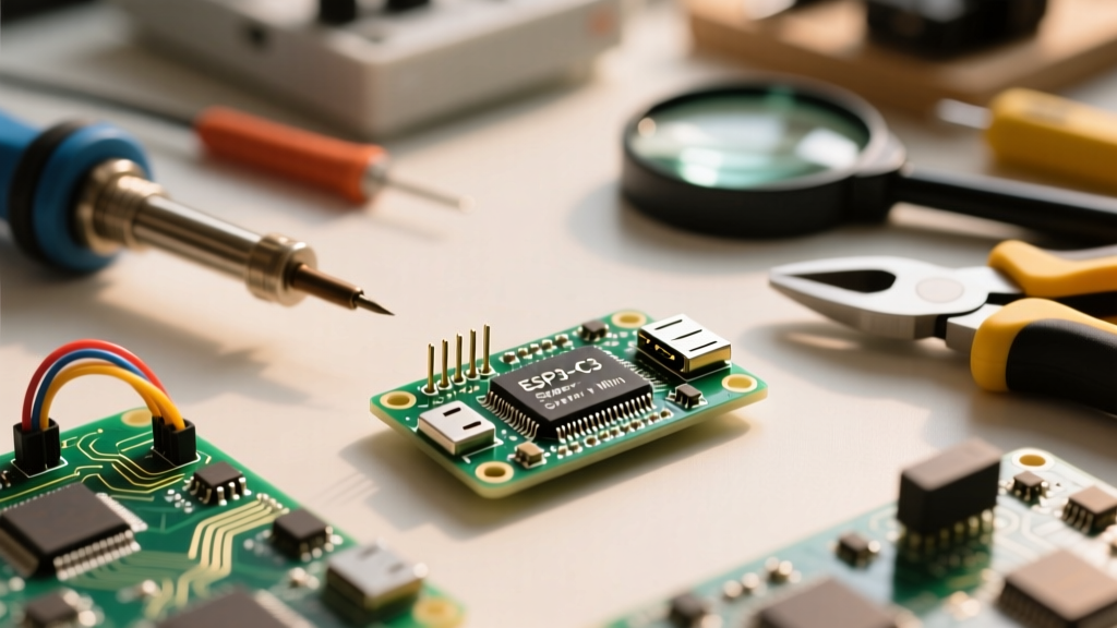
The ESP32 C3 Super Mini has taken the DIY electronics community by storm. Priced often under $3, this ultra-compact development board packs a single-core RISC-V processor, Wi-Fi 4, and Bluetooth 5.0 into a footprint barely larger than a postage stamp. However, its aggressive cost-reduction and miniaturization come with distinct hardware quirks that trip up beginners. Unlike full-sized DevKits, the Super Mini omits external UART chips and auto-reset circuits, relying entirely on the ESP32-C3's native USB capabilities.
This guide bypasses the generic fluff and dives straight into the real-world hardware realities, driver workarounds, and a practical first project to get your ESP32 C3 Super Mini running reliably.
Hardware Specifications & Pinout Reality
Before wiring up sensors, it is critical to understand what silicon is actually on the board. Most Super Mini variants use the ESP32-C3FH4 chip.
| Feature | Specification | Real-World Implication |
|---|---|---|
| Processor | RISC-V Single-Core @ 160 MHz | Excellent for IoT, but lacks the dual-core muscle for heavy DSP or audio processing. |
| Memory | 4MB Flash, 400KB SRAM | Sufficient for most MicroPython and Arduino sketches, including OTA updates. |
| Wireless | 802.11 b/g/n (Wi-Fi 4), BLE 5.0 | BLE 5.0 offers improved range and mesh capabilities over older ESP8266 modules. |
| USB Interface | Native USB-CDC (GPIO18, GPIO19) | No CH340/CP2102 chip. Requires specific OS drivers and manual boot modes. |
| Dimensions | 22.86 x 18.00 mm | Perfect for breadboards, but leaves no room for onboard voltage regulation beyond a basic LDO. |
The "Invisible Port" Problem: Fixing Native USB-CDC
The most common point of failure when setting up the ESP32 C3 Super Mini is plugging it in and seeing nothing in your Arduino IDE port list. Because this board uses the ESP32-C3's native USB-JTAG/Serial interface rather than an external USB-to-UART bridge, Windows often misidentifies it.
Windows Driver Fix
If your board shows up in Device Manager as an "Unknown Device" or a generic "USB Serial Converter" without a COM port number, follow these steps:
- Open Windows Device Manager.
- Locate the unrecognized USB device under Ports (COM & LPT) or Other Devices.
- Right-click and select Update driver.
- Choose Browse my computer for drivers -> Let me pick from a list of available drivers on my computer.
- Select Ports (COM & LPT), then choose USB Serial Device (or the Espressif CDC driver if you have the ESP-IDF tools installed).
- Assign it a COM port. It will now appear in Arduino IDE.
Note: macOS and Linux users typically do not face this issue; the board will mount natively as /dev/cu.usbmodem* or /dev/ttyACM0.
Overcoming the Bootloader Hurdle
Full-sized ESP32 boards use a clever circuit involving the DTR and RTS serial lines to automatically reset the chip and pull GPIO0 low to enter the bootloader. To save space and cost, the Super Mini omits this auto-reset circuit. You must manually force the board into download mode for your first flash.
The GPIO9 Manual Boot Sequence:
1. Press and hold the BOOT button (which grounds GPIO9).
2. While holding BOOT, press and release the RESET button.
3. Release the BOOT button.
The board is now in serial download mode and ready to receive firmware from the IDE.
After the initial successful upload, subsequent uploads will usually trigger the software bootloader automatically, provided your code initializes the USB-CDC correctly.
Arduino IDE 2.x Configuration
To program the ESP32 C3 Super Mini, you need the official Espressif Arduino core. You can track the latest releases on the Arduino ESP32 Core GitHub repository.
- Open Arduino IDE and navigate to Boards Manager.
- Search for
esp32and install the package by Espressif Systems (v2.0.14 or newer recommended). - Go to Tools > Board and select ESP32C3 Dev Module.
- Critical Step: In the Tools menu, set USB CDC On Boot to Enabled. If you leave this disabled, your board will flash successfully but will not output Serial prints or accept further uploads without manual boot mode intervention.
- Set Flash Mode to QIO and Partition Scheme to Default 4MB with spiffs.
First Project: Wi-Fi Connected BME280 Logger
For a practical first project, we will interface a BME280 environmental sensor via I2C, connect to Wi-Fi, and transmit the data. This tests the board's processing, wireless, and I2C peripherals simultaneously.
Wiring the Hardware
The ESP32-C3's default I2C pins on this specific board layout are GPIO6 (SDA) and GPIO7 (SCL).
- VIN: 5V from USB (or 3.3V if your sensor breakout has its own regulator)
- GND: Common Ground
- SDA: GPIO6
- SCL: GPIO7
Expert Tip: The ESP32-C3 has internal weak pull-up resistors, but for reliable I2C communication at 400kHz, use external 4.7kΩ pull-up resistors to 3.3V on the SDA and SCL lines.
The Firmware
Ensure you have the Adafruit_BME280 and Adafruit_Sensor libraries installed via the Library Manager.
#include <Wire.h>
#include <Adafruit_BME280.h>
#include <WiFi.h>

// Replace with your network credentials
const char* ssid = "YOUR_WIFI_SSID";
const char* password = "YOUR_WIFI_PASSWORD";

Adafruit_BME280 bme;

#define I2C_SDA 6
#define I2C_SCL 7

void setup() {
  Serial.begin(115200);
  while (!Serial) delay(10); // Wait for native USB CDC to connect

  // Initialize I2C with custom pins
  Wire.begin(I2C_SDA, I2C_SCL);

  if (!bme.begin(0x76, &Wire)) {
    Serial.println("Could not find a valid BME280 sensor, check wiring!");
    while (1) delay(10);
  }

  Serial.println("Connecting to WiFi...");
  WiFi.begin(ssid, password);
  while (WiFi.status() != WL_CONNECTED) {
    delay(500);
    Serial.print(".");
  }
  Serial.println("\nConnected! IP address: ");
  Serial.println(WiFi.localIP());
}

void loop() {
  float temp = bme.readTemperature();
  float hum = bme.readHumidity();
  float pres = bme.readPressure() / 100.0F;

  Serial.printf("Temp: %.2f C | Hum: %.2f %% | Press: %.2f hPa\n", temp, hum, pres);

  // In a real IoT scenario, send this via MQTT or HTTP POST here.

  delay(5000);
}
Advanced E-E-A-T: The Power LED Battery Hack
If you intend to run the ESP32 C3 Super Mini on a LiPo battery using the ESP32's famous deep sleep modes (which drop the chip's consumption to roughly 5µA), you will face a massive roadblock: the onboard power LED.
According to the Espressif ESP32-C3 Datasheet, the silicon itself is incredibly efficient. However, the Super Mini board features a red power LED tied directly to the 3.3V rail via a current-limiting resistor. This LED draws approximately 2.5mA to 3.0mA continuously.
To put this in perspective, a standard 1000mAh LiPo battery will be drained in less than 15 days by the LED alone, completely negating the deep sleep capabilities of the microcontroller. The Fix: Take an X-Acto knife or a small flathead screwdriver and carefully scratch off the LED component or sever the copper trace leading to it. This single physical modification transforms the board from a benchtoy into a viable, months-long battery-operated IoT node.
Antenna Performance & Keep-Out Zones
Unlike boards with external u.FL connectors or ceramic chip antennas, the Super Mini utilizes a PCB trace antenna. While surprisingly capable, it is highly sensitive to its environment. Ensure that the antenna overhang at the end of the board does not sit directly over a grounded metal surface or a dense breadboard power rail. Maintaining a 5mm keep-out zone around the antenna trace will prevent severe signal attenuation and dropped Wi-Fi packets.
Further Reading
- Espressif ESP32-C3 Hardware Reference - For deep dives into the RISC-V memory mapping and GPIO matrix.
- Waveshare ESP32-C3 SuperMini Wiki - Excellent alternative pinout diagrams and schematic references for the clone boards.