
The ESP32-C3 in the Modern Arduino Ecosystem
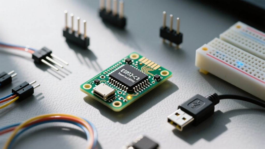
Since its introduction, the Espressif ESP32-C3 has fundamentally shifted the economics of the IoT and microcontroller ecosystem. Powered by a 32-bit RISC-V single-core processor clocked at 160 MHz, it was designed to be the direct, pin-compatible successor to the legendary ESP8266, but with modern security features and Bluetooth 5 (LE) support. In 2026, development boards like the Seeed Studio XIAO ESP32C3 (retailing around $6.99) and the official ESP32-C3-DevKitM-1 (around $8.50) are ubiquitous in both hobbyist and industrial deployments.
However, migrating from older 8-bit AVR boards or even the standard dual-core ESP32 introduces unique architectural quirks—especially regarding serial communication. When developers search for ways to optimize Arduino ESP32-C3 serial speed, they frequently encounter bottlenecks related to buffer overflows, native USB routing, and baud rate mismatches. Understanding how the Arduino core interacts with the C3’s specific hardware peripherals is critical for high-throughput data logging, GPS parsing, or RS-485 industrial communication.
Native USB vs. Hardware UART: Architectural Differences
Unlike the original ESP32 or the Arduino Uno, which rely on external USB-to-UART bridge chips (like the CP2102 or CH340), the ESP32-C3 features a built-in USB Serial/JTAG controller. This architectural choice drastically alters how serial speeds are handled within the Arduino IDE.
Expert Insight: In the Arduino-ESP32 core, the
Serialobject can map to either the native USB CDC (Communication Device Class) interface or the hardware UART0, depending on your IDE menu configuration. Confusing these two is the number one cause of perceived "serial speed limits" and dropped packets in C3 projects.
How the Routing Works
- Native USB CDC (USB Serial/JTAG): Bypasses external bridge chips entirely. The RISC-V core handles USB descriptors and packet framing in software/hardware hybrid. This is ideal for debugging and high-speed PC-to-MCU data transfer.
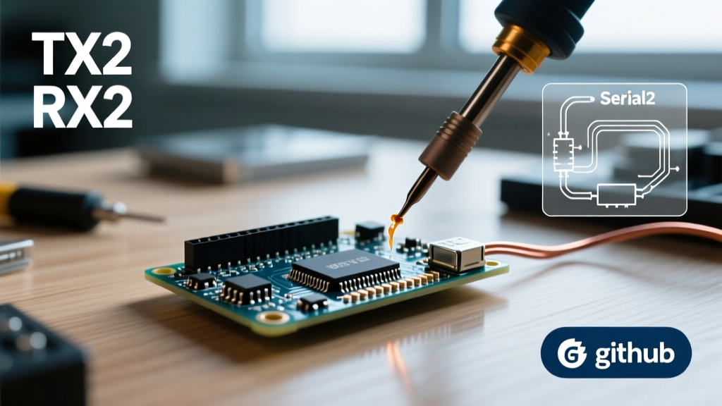
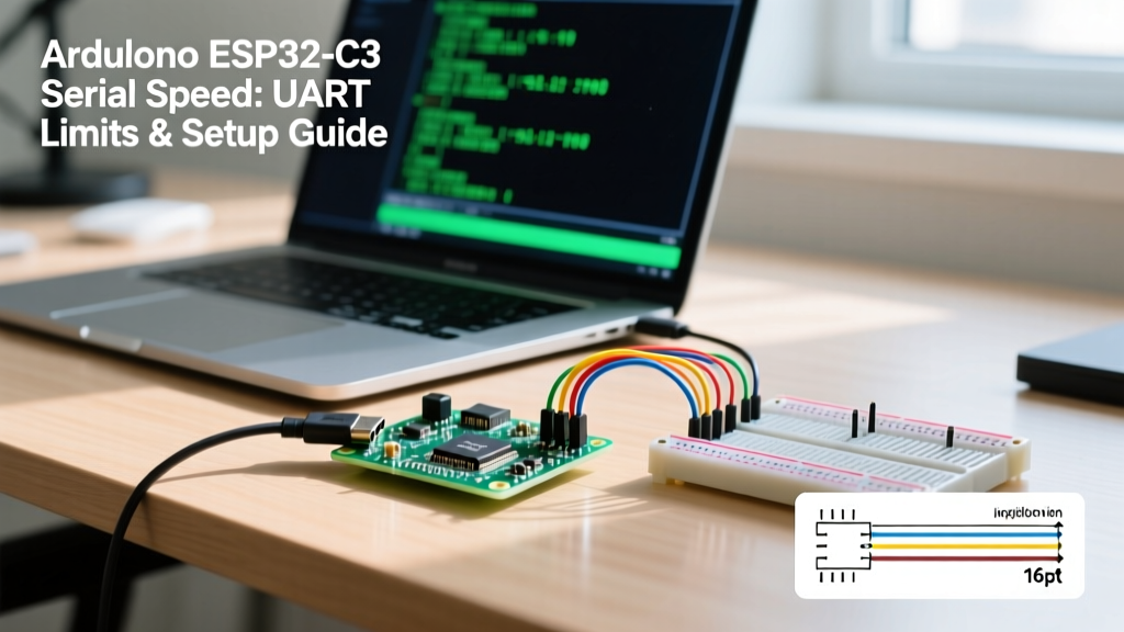
- Hardware UART (UART0 / UART1): Standard asynchronous serial lines (TX/RX). The ESP32-C3 has two primary UART controllers available for general use. These are used for communicating with external sensors (e.g., NMEA GPS modules, PMS5003 air quality sensors) or RS-485 transceivers.
Maximum Arduino ESP32-C3 Serial Speed Limits
What is the actual ceiling for serial throughput on this RISC-V chip? According to the Espressif ESP32-C3 Technical Reference Manual, the hardware UART controllers support baud rates up to 5 Mbps. However, theoretical limits rarely match real-world ecosystem constraints.
| Interface Type | Theoretical Max Baud | Practical Reliable Limit | Primary Bottleneck |
|---|---|---|---|
| Native USB CDC | ~12 Mbps (USB 1.1 Full Speed) | 3 Mbps - 5 Mbps | Host OS polling rate & USB stack overhead |
| Hardware UART0/1 (Direct) | 5 Mbps | 2 Mbps - 3 Mbps | Signal integrity, cable capacitance, receiver IC limits |
| Hardware UART (via USB Bridge) | 3 Mbps (CP2102N) | 921,600 bps - 2 Mbps | External bridge chip capabilities & driver buffers |
For standard telemetry and debugging, 115,200 bps or 460,800 bps remains the sweet spot. Pushing the Arduino ESP32-C3 serial speed beyond 2 Mbps on hardware UART requires careful attention to wiring length and baud rate tolerance, as the RISC-V core's clock dividers can introduce slight fractional errors at non-standard baud rates.
The 128-Byte FIFO Trap: Edge Cases and Failures
The most common failure mode when pushing high serial speeds on the ESP32-C3 is not the baud rate itself, but the hardware FIFO (First-In-First-Out) buffer. The C3’s UART RX FIFO is exactly 128 bytes.
Why Overruns Happen at High Speeds
If you configure Serial1.begin(3000000) to read from a high-speed LiDAR or FPGA, data floods the RX pin. The hardware moves bytes from the shift register into the 128-byte FIFO. The Arduino core relies on an interrupt service routine (ISR) to move bytes from the hardware FIFO into the software RingBuffer.
If your loop() function is heavily occupied—perhaps handling Wi-Fi stack events, driving NeoPixel LEDs (which disable interrupts), or performing intensive cryptographic TLS handshakes—the ISR may be delayed. If the 128-byte hardware FIFO fills up before the ISR can drain it, you get a UART FIFO Overrun Error, and bytes are permanently dropped.
Solutions for High-Speed Data Integrity
- Enable Hardware Flow Control: If your external device supports it, wire the RTS/CTS pins. This allows the C3 to signal the sender to pause transmission when the software buffer reaches 80% capacity.
- Avoid Interrupt-Blocking Code: Libraries like
Adafruit_NeoPixelfor the SK6812 LEDs disable global interrupts for precise timing. At 3 Mbps, a 100-microsecond interrupt block will drop roughly 30 bytes. Use DMA-driven LED libraries (likeFastLEDwith RISC-V I2S/SPI DMA) instead. - Use UART DMA (Advanced): While the standard Arduino
HardwareSerialclass abstracts this, advanced users leveraging the ESP-IDF API within the Arduino framework can configure UART DMA to bypass the 128-byte FIFO limit entirely, writing directly to SRAM.
Step-by-Step: Configuring High-Speed Serial in Arduino IDE
To ensure you are utilizing the correct interface and maximizing throughput, follow this configuration workflow in the Arduino IDE (v2.3+).
1. Select the Correct USB Mode
Navigate to Tools > USB CDC On Boot and select Enabled. This ensures that the native USB port acts as a virtual COM port, freeing up UART0 for external hardware communication.
2. Implementing the Code
/* High-Speed Serial Setup for ESP32-C3 */
#include

// Use UART1 for external high-speed sensor
HardwareSerial MySensor(1);

void setup() {
  // Native USB for PC debugging
  Serial.begin(115200);
  while(!Serial) { delay(10); }

  // Hardware UART1 at 2 Mbps (RX=4, TX=5)
  MySensor.begin(2000000, SERIAL_8N1, 4, 5);

  // Increase the software ring buffer from default 256 to 2048 bytes
  MySensor.setRxBufferSize(2048);

  Serial.println("C3 Serial Ecosystem Initialized.");
}

void loop() {
  // Bulk read to prevent FIFO overflow
  if(MySensor.available() > 128) {
    while(MySensor.available()) {
      Serial.write(MySensor.read());
    }
  }
}
Notice the use of setRxBufferSize(2048). By expanding the software ring buffer in the Arduino core, you give the RISC-V core a much larger safety net to absorb burst data traffic while the Wi-Fi radio handles background RF calibration.
Ecosystem Comparison: C3 vs. S3 vs. RP2040
How does the ESP32-C3's serial ecosystem compare to other popular boards in 2026? When selecting a platform for high-speed serial bridging, the choice of MCU dictates your architectural limits.
| Feature | ESP32-C3 (RISC-V) | ESP32-S3 (Xtensa Dual-Core) | Raspberry Pi RP2040 (Cortex-M0+) |
|---|---|---|---|
| Hardware UARTs | 2 (UART0, UART1) | 3 (UART0, UART1, UART2) | 2 (UART0, UART1) |
| Max Hardware Baud | 5 Mbps | 5 Mbps | ~921.6 kbps (Standard) / Higher with PIO |
| Native USB | USB Serial/JTAG (Fixed pins) | USB OTG (Native CDC/MSC) | USB 1.1 Controller (Native CDC) |
| FIFO Depth | 128 Bytes | 128 Bytes | 32 Bytes (Hardware) / DMA dependent |
| Best Use Case | Cost-effective IoT telemetry | High-bandwidth camera/audio bridging | Deterministic PIO-based custom serial protocols |
While the RP2040 offers the Programmable I/O (PIO) state machines—which can emulate virtually any serial protocol at massive speeds—the ESP32-C3 remains the undisputed king of low-cost, Wi-Fi-enabled serial bridging. As documented in the Arduino-ESP32 Core Repository, continuous optimizations to the RISC-V interrupt handling have made the C3 significantly more reliable at high baud rates than the older ESP8266, which suffered from severe non-maskable interrupt (NMI) conflicts with its Wi-Fi stack.
Final Troubleshooting Checklist for Serial Speed Issues
If you are experiencing garbage output or dropped packets when pushing the limits of your Arduino ESP32-C3 serial speed, verify the following:
- Baud Rate Drift: At 3 Mbps, a 1% clock tolerance error between the C3 and the receiving PC can cause framing errors. Stick to standard baud rates (e.g., 921600, 2000000) where the 160 MHz APB clock can divide evenly.
- USB Cable Capacitance: When using the native USB CDC interface at high throughput, cheap, unshielded USB-C cables can cause packet corruption. Use high-quality, shielded data cables rated for USB 2.0.
- Core Debug Level: Ensure Tools > Core Debug Level is set to None. Leaving this on "Verbose" forces the ESP32-C3 to output massive amounts of RTOS logging to UART0, which will instantly saturate the bus and cause your application-level serial data to stall or corrupt.
By respecting the 128-byte hardware FIFO, correctly routing native USB versus hardware UART, and leveraging the expanded software ring buffers available in the modern Arduino core, the ESP32-C3 proves itself as a highly capable, high-speed serial node in any IoT ecosystem. For further hardware pinout details and specific schematic references, developers can consult the Seeed Studio XIAO ESP32C3 Wiki to ensure their physical wiring supports the electrical demands of multi-megabit serial transmission.