
The Mechanics of Microsecond Timing
When you transition from blinking an LED to reading high-speed sensors or generating specific communication protocols, the standard delay() function is no longer sufficient. You need granular control over time. This is where the delayMicroseconds() function becomes essential. While a millisecond is one-thousandth of a second, a microsecond (µs) is one-millionth of a second. In the world of microcontrollers, a single microsecond is an eternity, allowing the processor to execute dozens of instructions.
To understand how to use delay Arduino microseconds effectively, you must first understand your board's clock speed. A standard Arduino Uno operates at 16 MHz, meaning it processes 16,000,000 clock cycles per second. Therefore, a single clock cycle takes exactly 0.0625 µs. To pause execution for just 1 µs, the microcontroller must execute roughly 16 assembly instructions. This hardware-level reality dictates the limits and accuracy of microsecond timing across different platforms.
delay() vs delayMicroseconds(): A Structural Comparison
Beginners often confuse the two primary timing functions. Below is a structural comparison to help you choose the right tool for your project.
| Feature | delay() | delayMicroseconds() |
|---|---|---|
| Base Unit | Milliseconds (ms) | Microseconds (µs) |
| Parameter Type | unsigned long (32-bit) | unsigned int (16-bit on AVR, 32-bit on ARM) |
| Max Accurate Value | ~49.7 days | 16383 µs (on 16MHz AVR) |
| Underlying Mechanism | Hardware Timer0 overflow | Software instruction loops |
| Interrupt Behavior | Interrupts remain active | Interrupts remain active (but cause jitter) |
For a deeper look into the official implementation, you can review the Arduino delayMicroseconds() reference and the standard delay() reference.
Hardware Limits Across Popular Boards
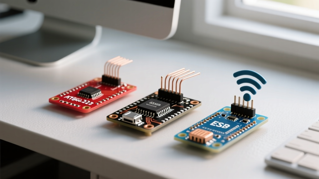
Not all microcontrollers handle microsecond delays identically. The underlying architecture drastically changes how the function behaves.
Arduino Uno (ATmega328P - AVR Architecture)
On 16 MHz AVR boards, delayMicroseconds() is highly accurate for values between 3 µs and 16383 µs. If you request a delay larger than 16383 µs, the function loses precision. For delays exceeding this threshold, you must switch to delay(). Furthermore, values smaller than 3 µs are unreliable due to the overhead of calling the function itself.
ESP32 (Xtensa LX6 / RISC-V Architecture)
The ESP32 operates at much higher clock speeds (typically 160 MHz to 240 MHz). The Arduino core for ESP32 maps this function to the underlying FreeRTOS and ESP-IDF ets_delay_us() or hardware timer loops. It is highly accurate, but because the ESP32 runs a background Real-Time Operating System (RTOS), aggressive use of blocking delays in the main loop can trigger the Task Watchdog Timer (WDT), causing the board to reset.
Raspberry Pi Pico (RP2040 - ARM Cortex-M0+)
The RP2040 runs at 125 MHz. Its implementation of delayMicroseconds() is exceptionally tight and accurate. However, for sub-microsecond timing (like driving high-speed LEDs), the RP2040's Programmable I/O (PIO) state machines are the preferred method, completely bypassing the main CPU cores.
Practical Application: Reading an HC-SR04 Ultrasonic Sensor
The most common beginner use case for microsecond delays is triggering the HC-SR04 ultrasonic distance sensor. The sensor requires a precise 10 µs HIGH pulse on its Trigger pin to initiate a sonic burst.
const int trigPin = 9;
const int echoPin = 10;

void setup() {
  Serial.begin(9600);
  pinMode(trigPin, OUTPUT);
  pinMode(echoPin, INPUT);
}

void loop() {
  long duration;
  float distance;

  // Clear the trigger pin
  digitalWrite(trigPin, LOW);
  delayMicroseconds(2);

  // Generate the 10µs trigger pulse
  digitalWrite(trigPin, HIGH);
  delayMicroseconds(10);
  digitalWrite(trigPin, LOW);

  // Read the echo pin
  duration = pulseIn(echoPin, HIGH);

  // Calculate distance in cm (speed of sound / 2)
  distance = duration * 0.034 / 2;

  Serial.print("Distance: ");
  Serial.print(distance);
  Serial.println(" cm");

  delay(50); // Wait 50ms before next reading
}
Notice the delayMicroseconds(2) before the trigger pulse. This ensures the pin is definitively in a LOW state, providing a clean rising edge for the sensor's internal logic to detect. According to the ATmega328P datasheet, GPIO pin state changes take 1 to 2 clock cycles; the 2 µs delay guarantees the hardware has settled.
Critical Edge Cases and the 'Blocking' Trap
As you integrate microsecond delays into larger projects, you will encounter edge cases that can silently break your code.
The Negative Number Catastrophe
The delayMicroseconds() function accepts an unsigned int. If you calculate a delay dynamically and the math results in a negative number (e.g., -5), the compiler will cast this to an unsigned integer. On a 16-bit AVR, -1 becomes 65535. On a 32-bit ESP32, it becomes 4294967295. Your code will not crash; instead, it will hang for milliseconds or even hours. Always validate your variables to ensure they are strictly positive before passing them to the delay function.
Interrupt Jitter
Unlike some older low-level assembly routines, the modern Arduino delayMicroseconds() does not disable interrupts. If an interrupt service routine (ISR) fires while your microsecond delay is running, the delay will be extended by the execution time of the ISR. If you are generating a strict communication protocol (like the 38kHz carrier wave for IR remotes), this jitter will corrupt the signal.
The WS2812B (NeoPixel) Limitation
Beginners often attempt to write their own code for WS2812B addressable LEDs using delayMicroseconds(). The WS2812B protocol requires a bit-period of exactly 1.25 µs, with '0' and '1' defined by HIGH/LOW ratios within that window. Because function call overhead and interrupt jitter on AVR boards exceed the acceptable tolerance of ±150ns, software-based microsecond delays will fail. You must use dedicated libraries (like FastLED or Adafruit NeoPixel) which utilize hardware timers, direct port manipulation, or PIO state machines to guarantee timing.
Summary Best Practices
- Use for 3µs to 16000µs: Keep your values within the accurate window for AVR boards.
- Switch to delay() for longer pauses: If you need 20ms (20,000µs), use
delay(20)instead ofdelayMicroseconds(20000). - Avoid in the main loop: Microsecond delays are blocking. For non-blocking timing, use the
micros()function combined with state-machine logic. - Watch your data types: Ensure the variable passed to the function cannot mathematically evaluate to a negative number.
Mastering microsecond timing bridges the gap between basic hobbyist projects and professional-grade embedded systems. By respecting the hardware limits and understanding the underlying clock cycles, you can reliably interface with high-speed sensors and precision protocols.