
The Anatomy of the Pin Layout Arduino Uno Standard
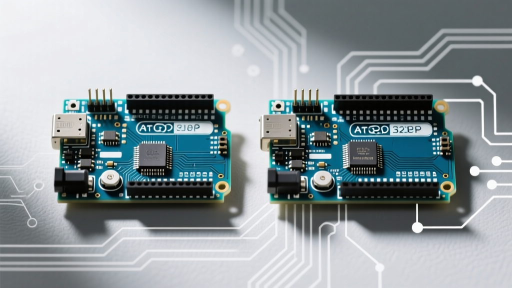
When designing custom shields or wiring complex sensor arrays, understanding the exact pin layout Arduino Uno standard is non-negotiable. Since its inception, the Uno footprint has become the undisputed universal standard for microcontroller development. However, as we navigate the electronics market in 2026, the physical and electrical realities of this layout vary wildly depending on whether you are using a $5.50 budget clone or a $27.50 premium original board.
The standard layout features 14 digital I/O pins and 6 analog inputs arranged in two female header rows. But the true test of a board's manufacturing quality lies in the microscopic tolerances of these headers, the accuracy of the silkscreen, and the thermal limits of the voltage regulators tied to the power pins. Let us break down how budget and premium boards interpret this iconic blueprint.
The 0.16-Inch Quirk: A Legacy Routing Mistake
Before comparing manufacturers, every maker must understand the most infamous quirk of the Uno layout: the spacing between Digital Pin 7 and Digital Pin 8. While all other adjacent pins are separated by a standard 0.1 inches (2.54mm), the gap between pins 7 and 8 is exactly 0.16 inches (4.06mm).
Expert Insight: This anomaly originated as a PCB routing mistake on the earliest Arduino Diecimila boards. Rather than breaking backward compatibility with existing shields, Arduino kept the mistake. According to the Arduino Uno Rev3 Documentation, this offset is now a mandatory mechanical requirement for shield compatibility.
How different manufacturers handle this 0.16-inch gap is the first major dividing line between budget and premium boards.
Budget Clones (Sub-$8): Pin Layout Pitfalls & Quirks
Budget clones, typically sourced via AliExpress or Amazon storefronts, utilize the CH340G USB-to-serial chip and cheaper PCB fabrication houses. While they functionally mirror the ATmega328P schematic, their physical pin layouts often introduce severe mechanical and electrical friction.
1. The "Fixed" Gap Problem
Many ultra-cheap clones attempt to "correct" the 0.16-inch gap between pins 7 and 8, standardizing it to 0.1 inches. While this seems logical, it instantly renders the board incompatible with rigid, hard-soldered shields. If you force a standard shield onto these clone pins, you will bend the shield's header pins, causing intermittent connections or snapping the traces.
2. Silkscreen Inaccuracies and Fading
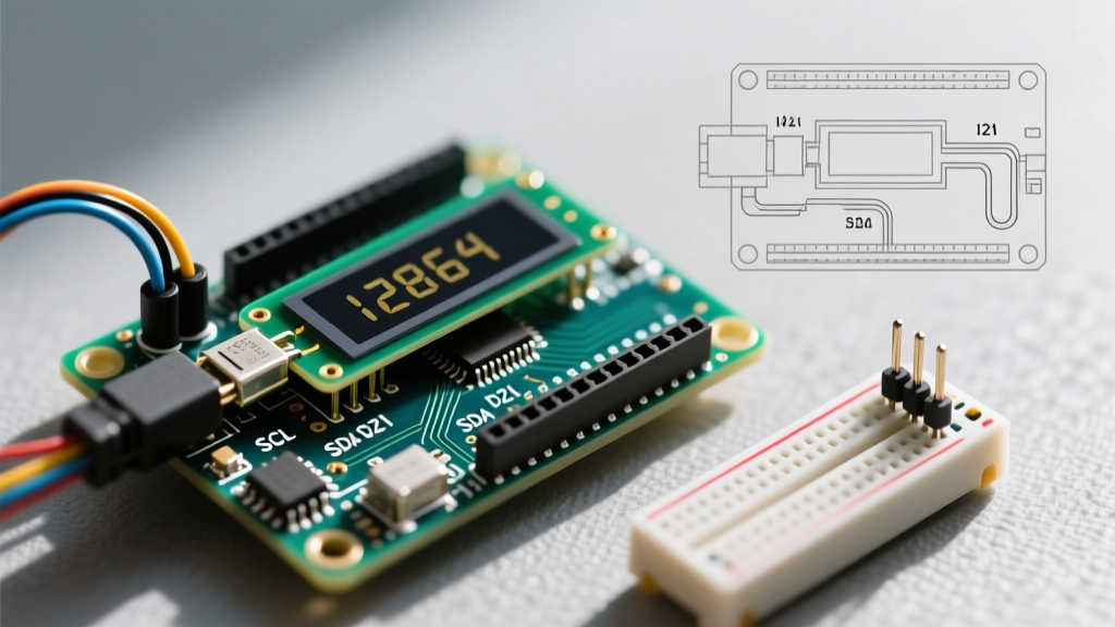
On budget boards, the silkscreen layer is often misaligned by up to 1.5mm. In 2026, we still see clones where the SDA and SCL labels near the AREF pin are printed over the analog pins rather than the dedicated I2C headers. Furthermore, cheap epoxy-based silkscreen ink flakes off after repeated shield insertions, leaving you guessing which power rail is 5V and which is VIN.
3. Voltage Regulator Thermal Limits
The physical pin layout includes the 5V and VIN power pins. Budget clones almost universally use the AMS1117-5.0 linear regulator. While rated for 1A on paper, the minimal copper pour on clone PCBs acts as a poor heatsink. Pushing more than 350mA through the 5V pin on a budget clone will trigger thermal shutdown, causing the microcontroller to brownout and reset.
Premium Boards ($20-$35): Precision and Enhanced Pinouts
Premium boards include the official Arduino Uno R4 Minima ($19.90), the Uno R3 ($27.50), and high-end third-party alternatives like the Adafruit Metro 328 or SparkFun RedBoard. These boards treat the pin layout as a precision mechanical interface.
Exact Tolerance and Gold Flash Headers
Premium boards adhere strictly to the 0.16-inch offset between pins 7 and 8. Furthermore, they use gold-flash plated female headers. This reduces contact resistance to under 20 milliohms and prevents oxidation, ensuring that a shield snapped onto the board in 2026 will maintain a flawless connection through thousands of insertion cycles.
Enhanced I2C and Power Pads
As documented in the Adafruit Metro Pinouts Guide, premium alternatives often add duplicate breakout pads for the I2C pins (SDA/SCL) in the standard 0.1-inch grid, bypassing the awkward offset of the R3 layout. Additionally, premium boards utilize high-efficiency switching regulators or robust NCP1117 LDOs with extensive thermal vias, allowing the 5V pin to safely source 800mA to 1A continuously.
The Uno R4 Additions
The official Arduino Uno R4 Minima maintains the exact legacy shield footprint but adds an SWD (Serial Wire Debug) 4-pin header and a VUSB jumper pad near the VIN pin. This allows advanced users to bypass the onboard 5V regulator entirely and draw power directly from the USB-C bus, a critical layout enhancement for high-current LED matrix projects.
Comparison Matrix: Budget vs. Premium Pin Layouts
| Feature | Budget Clone (CH340G) | Original Uno R3 | Uno R4 Minima |
|---|---|---|---|
| Average Price (2026) | $4.50 - $7.00 | $27.50 | $19.90 |
| Pin 7-8 Spacing | Inconsistent (Often 0.1") | Exact 0.16" (4.06mm) | Exact 0.16" (4.06mm) |
| Header Material | Tin-plated (Prone to oxidation) | Gold-flash plated | Gold-flash plated |
| 5V Pin Safe Current | ~350mA (Thermal limited) | ~800mA | 1A+ (Switching regulator) |
| Silkscreen Durability | Low (Fades/Flakes) | High (Epoxy cured) | High (Epoxy cured) |
| Extra Debug Pins | ICSP only | ICSP only | ICSP + 4-pin SWD Header |
Troubleshooting: Fixing Clone Shield Seating Issues
If you are forced to use a budget clone for a high-volume deployment and encounter the "wobbly shield" issue caused by misaligned headers or the incorrect 0.1-inch gap, you can mechanically correct the layout using a technique called jig-reflowing.
- Procure a Sacrificial Shield: Use a cheap, bare protoshield with standard 0.1-inch male headers soldered perfectly straight.
- Apply Liquid Flux: Coat the male header pins of the sacrificial shield with high-quality tacky flux (e.g., Amtech NC-559).
- Mate the Boards: Push the clone board's female headers onto the sacrificial shield. This forces the clone's pins into perfect, standardized alignment.
- Reflow the Clone: Using a soldering iron set to 350°C (662°F) and a chisel tip, touch the base of each female header pin on the clone board for exactly 2 seconds. The existing solder will melt, allowing the header to settle into the exact geometry dictated by the sacrificial shield.
- Cool and Separate: Allow the board to cool completely to room temperature before pulling the shield off. Your clone now has perfectly parallel headers, mitigating mechanical stress on your primary project shield.
Frequently Asked Questions (FAQ)
Can I use 3.3V logic sensors on the 5V pins of a budget clone?
No. The pin layout on both budget and premium Unos routes the digital I/O directly to the ATmega328P (or RA4M1 on the R4), which operates at 5V. Connecting a strict 3.3V sensor (like the BME280 or certain LiDAR modules) directly to Digital Pin 2-13 will fry the sensor. You must use a bidirectional logic level converter, regardless of whether you are using a $5 clone or a $28 premium board.
Why do some premium boards like the SparkFun RedBoard have extra pins near the I2C layout?
Third-party premium manufacturers recognized the bottleneck of the original R3 I2C layout. As detailed in the SparkFun RedBoard Qwiic specifications, premium variants often integrate a 4-pin Qwiic/Stemma QT connector directly adjacent to the standard I2C pins. This allows daisy-chaining modern I2C sensors without utilizing the main pin layout headers at all, freeing up physical space for other shields.
Does the CH340G chip on clones affect the TX/RX pin layout behavior?
Electrically, the TX (Pin 1) and RX (Pin 0) routing remains identical. However, the CH340G chip lacks the hardware flow control and auto-reset capacitor tuning found in the premium ATmega16U2 chip. This means that on budget clones, you may occasionally need to manually press the hardware reset button exactly as the IDE finishes compiling, because the DTR signal on the auto-reset pin isn't timed perfectly to trigger the bootloader.
Final Verdict: Which Layout Should You Design For?
If you are designing a PCB shield intended for mass distribution or educational kits, you must design for the exact 0.16-inch offset and standard 0.1-inch grid of the premium Original Uno R3/R4 layout. Designing around the quirks of budget clones will alienate users with genuine hardware. However, if you are wiring a one-off permanent installation where the board will be hard-soldered and buried in an enclosure, a $5 budget clone provides the exact same schematic pinout, provided you respect the lower 350mA thermal limit on the 5V power pin.