
The Physical Reality: Why Arduino Uno Dimensions Matter
When beginners start their electronics journey, the focus is almost entirely on code and breadboard wiring. However, the transition from a messy desk prototype to a finished, reliable device requires confronting the physical reality of hardware. Understanding exact Arduino Uno dimensions is the critical first step in designing custom enclosures, selecting off-the-shelf project boxes, and ensuring your components actually fit before you start drilling plastic or printing 3D housings.
In this setup and first-project tutorial, we will break down the precise X, Y, and Z-axis measurements of the Uno footprint. Then, we will apply this data to build a Desktop Air Quality & Climate Monitor using an Arduino Uno R4 Minima, a BME280 sensor, and an I2C OLED display, housing it all in a professionally sized enclosure.
Official Arduino Uno Footprint & Bounding Box
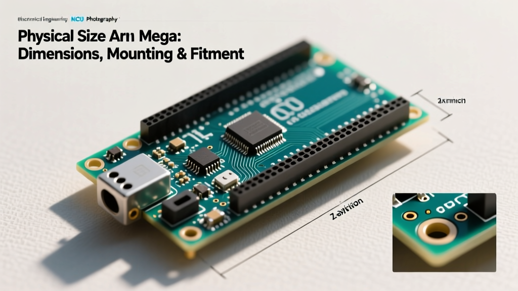
The 'Uno' form factor is the most cloned and supported physical footprint in the microcontroller world. Whether you are using the legacy Uno R3 or the modern Uno R4 series, the PCB mounting holes remain standardized. However, the bounding box—the total volume the board occupies including overhanging ports—changes depending on the revision.
| Measurement Axis | Specification (PCB Only) | Total Bounding Box (with Ports) |
|---|---|---|
| Length (X-Axis) | 68.6 mm (2.70 inches) | 84.6 mm (Includes USB Type-B overhang) |
| Width (Y-Axis) | 53.4 mm (2.10 inches) | 53.4 mm (No lateral overhang) |
| Height (Z-Axis) | 1.6 mm (PCB thickness) | ~48.0 mm (Includes female headers & USB) |
| Weight | ~25 grams (Board only, no shields attached) | |
The Mounting Hole Matrix
For enclosure design, the PCB dimensions are secondary to the mounting hole spacing. The Uno utilizes four M3 (3.2mm diameter) mounting holes. If you are 3D printing an enclosure or milling a custom acrylic baseplate, use these exact center-to-center distances:
- Hole 1 (Top Left): 15.2 mm from left edge, 50.8 mm from bottom edge.
- Hole 2 (Top Right): 66.1 mm from left edge, 35.6 mm from bottom edge.
- Hole 3 (Bottom Right): 66.1 mm from left edge, 7.6 mm from bottom edge.
- Hole 4 (Bottom Left): 13.9 mm from left edge, 7.6 mm from bottom edge.
Note: The asymmetrical placement is a legacy design choice from 2005 that the industry has maintained for backward compatibility. Always verify against the Arduino Official Documentation before finalizing CAD files.
2026 Hardware Context: Uno R3 vs. Uno R4 Minima
As of 2026, the Arduino Uno R4 Minima (retailing around $27.50) has largely superseded the R3 for new project setups. While the PCB footprint (68.6 x 53.4 mm) and mounting holes are identical, the Z-axis and X-axis overhangs differ slightly:
- USB Overhang: The R3 uses a bulky USB Type-B connector that protrudes ~16mm past the PCB edge. The R4 Minima uses a USB-C port, reducing the X-axis overhang to just ~8mm. This allows the R4 to fit into shallower enclosures.
- Component Clearance: The R4 features a Renesas RA4M1 processor and an SMD inductor that sits slightly taller than the R3's DIP ATmega328P, requiring a minimum Z-axis clearance of 20mm above the PCB before adding shields.
First Project: Desktop Climate & Air Quality Monitor
To put these dimensions into practice, we will build a compact environmental monitor. This project requires precise enclosure selection because we must account for the Uno, the sensor wiring, and a flush-mounted display.
Bill of Materials (BOM)
- Microcontroller: Arduino Uno R4 Minima ($27.50)
- Sensor: Adafruit BME280 I2C Breakout ($15.00) - Adafruit BME280 Guide
- Display: 0.96-inch I2C OLED (128x64, SSD1306 driver) ($12.00)
- Enclosure: Hammond 1591XXTBK ABS Project Box ($9.50) - Hammond 1591 Series Specs
- Hardware: M3x12mm nylon standoffs and screws ($4.00)
Enclosure Math: Will it Fit?
The Hammond 1591XX series is an industry standard for DIY electronics. Let us run the dimensional math to ensure our Uno setup fits inside the 1591XXTBK model.
Internal Dimension Calculation
- External Enclosure Size: 120 x 120 x 55 mm
- Internal Usable Width (Y): ~110 mm. Result: Easily clears the Uno's 53.4mm width, leaving 56mm for the BME280 sensor and wire routing.
- Internal Usable Length (X): ~110 mm. Result: Clears the Uno's 84.6mm max bounding box (with R3 USB overhang) with 25mm to spare for panel-mount switches.
- Internal Usable Depth (Z): ~50 mm. Result: Uno PCB (1.6mm) + Standoff (12mm) + Header Pins (8.5mm) + Jumper Wires (15mm) = 37.1mm. Leaves 12.9mm for the OLED screen and lid clearance.
Step-by-Step Assembly & Setup
Step 1: Preparing the Enclosure Lid
The 0.96-inch OLED display has an active viewing area of roughly 27mm x 15mm, but the PCB module itself is 27mm x 28mm. Use a caliper to mark a 27mm x 15mm rectangle on the center of the Hammond enclosure lid. Drill four 2mm pilot holes at the corners of your rectangle, then use a jeweler's saw or a Dremel with a cutting wheel to remove the plastic. File the edges smooth. Secure the OLED from the inside using double-sided Kapton tape or small dabs of hot glue on the non-conductive edges of the display PCB.
Step 2: Mounting the Arduino
Do not rest the Uno directly on the plastic floor of the enclosure; this risks short-circuiting the exposed vias on the bottom of the PCB against any stray conductive debris or anti-static bag remnants. 1. Screw four M3x12mm nylon male-female standoffs into the pre-drilled lid boss points (if using the lid as a base) or into the base of the enclosure. 2. Align the Uno's four mounting holes with the standoffs. 3. Secure the board using four M3x6mm nylon screws. The nylon hardware prevents grounding loops and protects the PCB traces from being crushed by overtightening.
Step 3: Wiring the I2C Bus
Both the BME280 and the OLED utilize the I2C protocol, meaning they share the same data lines, keeping our physical footprint incredibly clean. Connect the following pins from the Uno R4 Minima to a small 4-channel I2C breakout hub or directly via silicone jumper wires:
- 5V: VCC on OLED and VIN on BME280
- GND: GND on both modules
- SDA (Pin A4 on R3 / Dedicated SDA on R4): SDA on both modules
- SCL (Pin A5 on R3 / Dedicated SCL on R4): SCL on both modules
Crucial Edge Case: The BME280 breakout usually has a 3.3V voltage regulator onboard, allowing it to accept 5V on the VIN pin. However, the I2C data lines (SDA/SCL) will be pulled up to 3.3V by the sensor board. The Uno R4 operates natively at 5V logic but is generally I2C tolerant of 3.3V pull-ups. If you experience display flickering, add a bidirectional logic level converter (like the BSS138) between the Uno and the BME280.
Common Physical Pitfalls to Avoid
The 'Shield Stacking' Z-Axis Trap: Beginners often buy an enclosure based solely on the bare Uno dimensions, forgetting that adding a prototyping shield or a motor driver shield adds exactly 15.5mm to the Z-axis height. Always measure your fully stacked assembly with calipers before ordering project boxes.
Another frequent failure mode is USB port accessibility. If you are cutting a slot in the side of an ABS enclosure for the USB cable, remember that the USB Type-A connector on the cable itself adds ~15mm of rigid length. Ensure your enclosure is placed far enough from walls or desk edges, or use a 90-degree USB adapter to route the cable flush against the enclosure wall.
Final Thoughts on Hardware Design
Mastering Arduino Uno dimensions is about more than just memorizing 68.6mm by 53.4mm. It is about understanding the three-dimensional bounding box, the legacy mounting matrix, and how modern iterations like the R4 alter the physical envelope. By calculating internal enclosure clearances and planning for Z-axis wire bends, your first project transitions from a fragile breadboard experiment into a robust, desktop-ready instrument.